
7.3 Powerstroke Overboost Code Regulator: Full Step By Step How To
Nov 6th 2025
Full PDF Instructions can be downloaded here: https://www.riffraffdiesel.com/content/RESOURCES/OCR_Installation_Instructions.pdf
Required Parts:
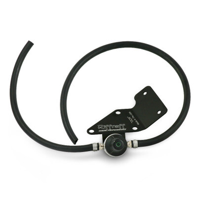
OCR - Overboost Code Regulator™ 99-03
OCR - Overboost Code Regulator™ 94-97
Required Tools:
- 10mm deep well socket
- Torx T20 socket tip or screwdriver (can also use a flat tip screwdriver)
- Large flat-blade screw driver (only if you don’t have a T20 driver)
- Standard pliers
Recommended Supplies:
- Electrical tape
- Wire loom
IMPORTANT: Before starting installation, please be sure that all items that were supplied with the kit are accounted for.
1. Disconnect and/or remove the following components (refer to pictures for locations):
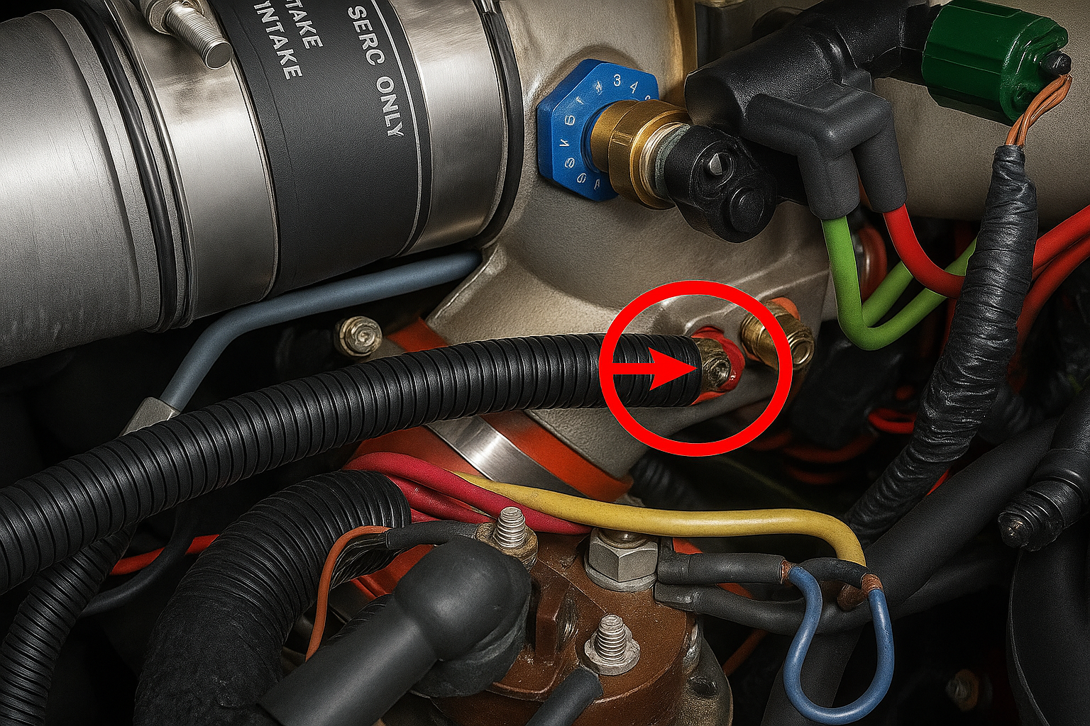
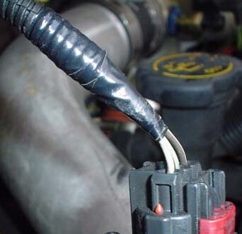
- Using pliers, open and slide the red hose clamp back up the hose and pull the hose off the nipple on the intake spider. This hose supplies a boost reference for the MAP sensor.
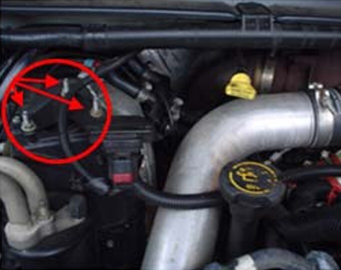
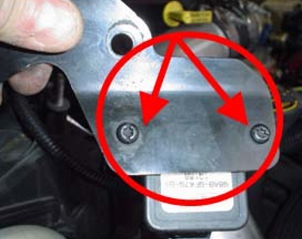
- Using the 10mm socket, remove the three screws holding the MAP sensor bracket in place.
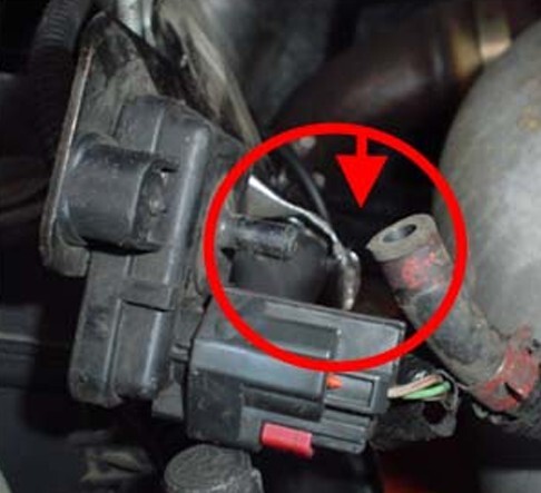
- As in “a”, remove the clamp & hose from the MAP sensor.
2. If the tape on your wire loop is loose from age, this is the time to remove the old tape and replace it with new.
3. Using either the T20 driver or flat blade screwdriver, remove the two screws that hold the MAP sensor to the sensor bracket. If you want, you can discard the sensor bracket as it will no longer be required.
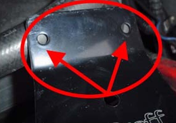
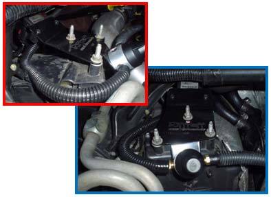
4. This first picture shows where the MAP sensor must be mounted on the new bracket from Riffraff Diesel’s OCR kit. The bottom picture shows the proper orientation for the sensor so it will fit under the cowl when mounting the new OCR bracket back into position.
5. Re-using one of the original hose clamps, attach the shorter of the two hoses from the OCR pressure regulator onto the connection on the MAP sensor.
IMPORTANT: Before attaching the new OCR bracket onto the three bolts where the original sensor bracket was mounted, do some trial and error test fits with the hoses and trim the hoses for optimum fit.
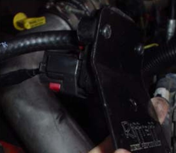
6. Once the proper hose lengths are determined and the hoses are trimmed for optimum fit, mount the new OCR bracket onto the three bolts where the original sensor bracket was mounted.
Suggestion: If the short hose is making contact against either a hard bracket or the hard aluminum tubing going to the Air Conditioner dryer, you might need to install some wire loom around the shorter of the two new hoses to minimize potential damage from vibration.
7. Re-install the wire loom around the new, longer hose.
8. Re-install the second of the original hose clamps on the new longer hose and reattach the hose to the nipple on the spider.
Credit for pictures and information to F250_ and the whole FTE crew. Thanks!


