
The “Non-Serviceable HPOP Plug” - Step By Step How To
Mar 11th 2026
If the non-serviceable plug at the bottom of your HPOP is leaking, the factory short-thread plug has likely stripped the threads in the aluminum housing.
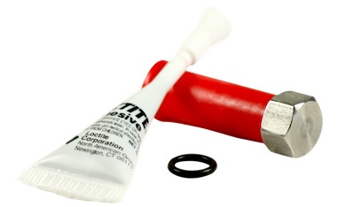
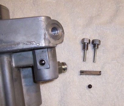
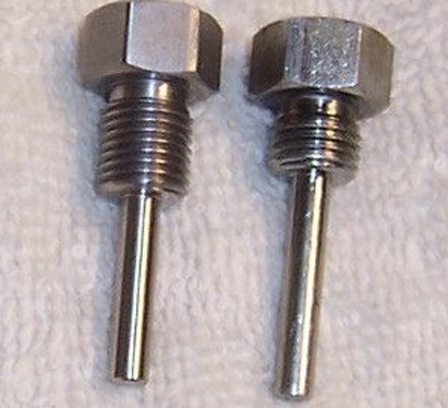
This long-thread replacement plug is made from high-quality 303 stainless steel and machined to exact Navistar specs. It is designed to repair stripped HPOP plug threads, even when the factory threads are completely gone. Includes a new O-ring, a 0.5 mL packet of Loctite 680 retaining compound, and is made in the USA.
Let's dive into the install:
Parts Link:
Serviceable Long Threaded HPOP Plug for Ford 7.3L (94-03)
Section A: Pump removal
Section B: Pump reinstallation / reassembly
General warning (critical)
To replace this plug, the HPOP must be removed from the engine first. Do not attempt to remove the non-serviceable plug while the pump is still installed else serious damage may occur.
Note about fuel bowl
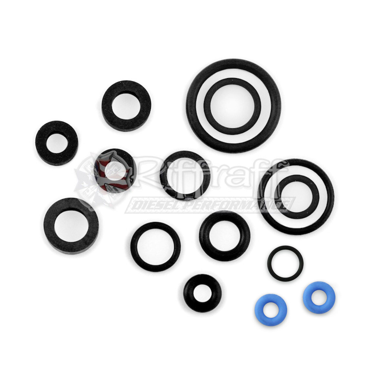
The fuel bowl canister is commonly removed first to improve access. Fuel hard line seals/sleeves at the fuel bowl are not reusable; a replacement seal kit is available: fuel bowl kit #7-003.
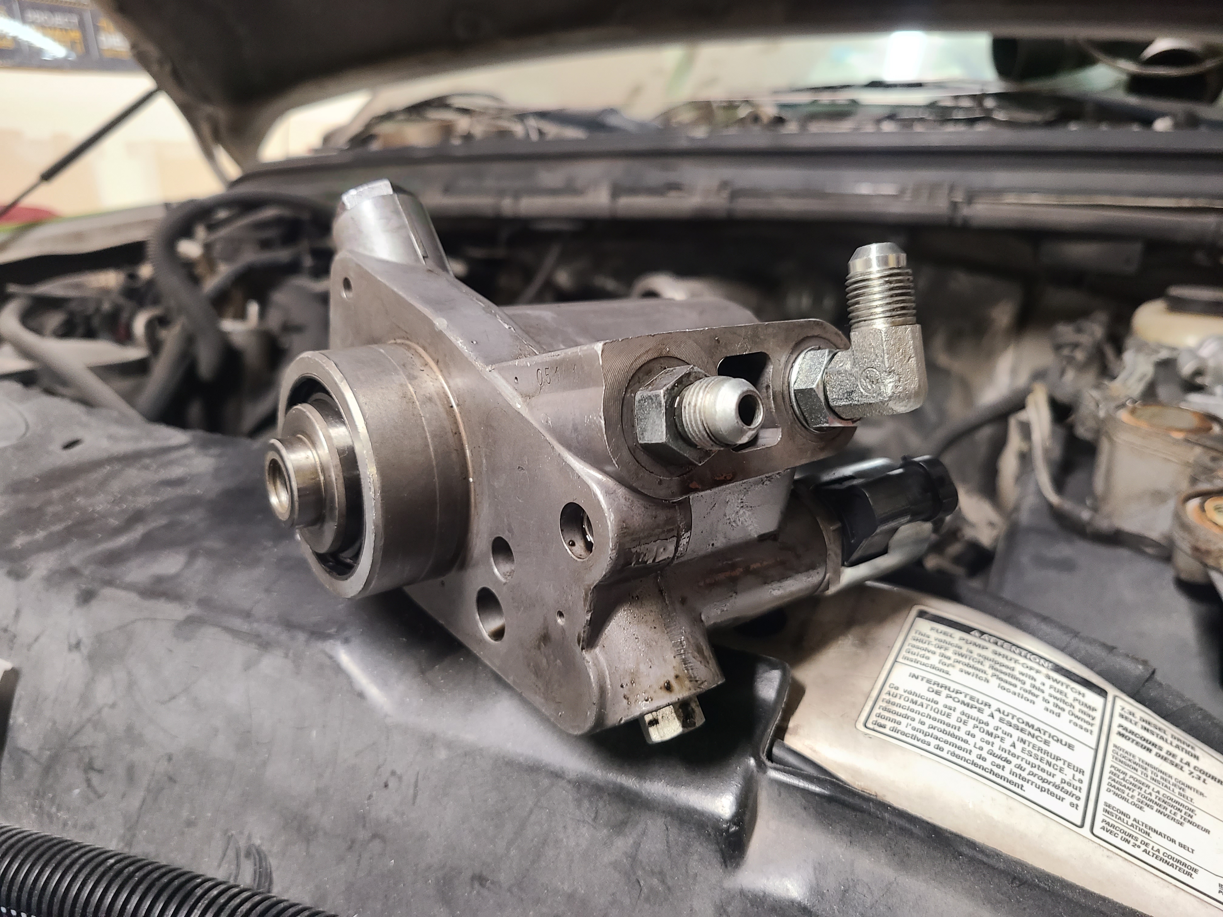
SECTION A — Removal of the pump
1A. Before unbolting the pump from the front engine plate, pull as much oil as possible out of the HPOP reservoir using a hand vacuum pump through the top reservoir plug.
2A. Disconnect both high-pressure discharge hoses from the pump (see HPOP kit #8-002 instructions).
3A. Remove the reservoir top cover (the larger bolts) to expose the HPOP drive gear. The small torx screws holding the cover halves together do not need to be removed.
4A. Remove the drive gear bolt access plate from the front engine cover. Remove the shaft bolt and remove the drive gear.
5A. Remove the two mounting bolts at the rear of the HPOP.
6A. Remove the pump from the engine bay. Use a deep 1-1/8 inch socket to remove the IPR from the rear of the pump. Have a drain pan/bucket ready for remaining oil.
7A. Let the pump drain into the pan.
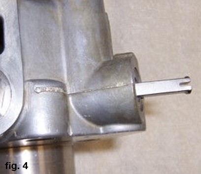
8A. Support the pump in a soft-jaw vise (or support it by placing the shaft into the drive gear you removed). The pump must be oriented with the shaft and milled surface facing down and the large plate with the snap ring/C-clip facing up. This helps keep the check ball and edge filter in place.
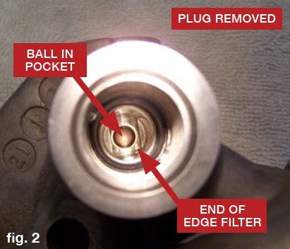
9A. Looking through the IPR threaded opening, you can see the edge filter end and a small ball that can be lost if the plug is removed while the pump is still on the engine.
10A. If the non-serviceable plug is tight, heat the end of the plug to approximately 400–500°F to soften the retaining compound so the plug can be removed with less chance of thread damage.
11A. After removing the non-serviceable plug, remove the check ball and edge filter.
Tip: work over a box so the ball doesn’t roll away if it drops. If the ball sticks due to oil, you can use compressed air through the small hole on the front of the pump (opposite the ball seat) to dislodge it.
Set the ball and edge filter aside safely.
12A. Through the plug opening you can see the recessed edge filter. The edge filter is the same on both ends, so orientation is not special.
13A. Using non-chlorinated brake cleaner, clean and degrease the threads in the plug opening, the discharge fittings (if removed), and the IPR opening. Let them dry fully. The threads need to be oil-film free so the retaining compound can bond.
14A. Inspect the cavity for leftover aluminum debris or old retaining compound; flush with brake cleaner and let dry. Ensure plug, pump threads, and fittings are clean and oil-free.
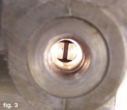
15A. Reinstall the edge filter through the new serviceable plug opening. Keep the pump oriented with the shaft down and the rear plate/snap ring pointing up. Cover the plug opening with your thumb and drop the ball into the IPR threaded opening. Use a flashlight through the IPR opening to confirm the ball is centered in its pocket at the front of the pump.
16A. Install the new plug o-ring. Rolling it over the threads is preferred versus stretching it.
17A. If pump threads are distorted/torn: use a cotton swab to put a very small amount of Loctite 680 onto clean “good” threads deep in the pump, since damaged threads can wipe compound off the plug before it reaches those good threads.
Then apply Loctite 680 to only the first four threads of the long threaded plug. Apply lightly—avoid excess; no drips should form.
18A. Start threading the new plug in, being careful not to push the ball out of its pocket. Only thread the plug in 2–3 turns at first, then stop.
Important warning
If the ball is pushed out of position, it can be crushed or end up on the wrong side of the plug’s pin. The engine may never start, and the ball can become stuck in the IPR and may have to be destroyed to remove it.
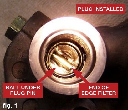
19A. With a flashlight, look through the IPR opening and verify the ball is below the plug pin (you should be able to see the ball on both sides of the pin).
20A. Torque the serviceable plug to 75 in-lb using an inch-pound torque wrench.
21A. If discharge fittings were removed, reinstall per kit #8-002 directions.
Cure time warning
For a long-term repair, allow Loctite 680 to cure for 24 hours before oil is reintroduced.
Best practice: leave the pump on the bench with the plug facing up so draining oil doesn’t contaminate the compound during cure.
SECTION B — Reinstalling the pump
Note for late 1994 / early 1995 applications: The replacement plug may be slightly longer than the original; This won’t affect operation/installation because that pump version does not use an edge filter.
1B. Clean any remaining sealant from the reservoir gear cover plate and the front engine cover.
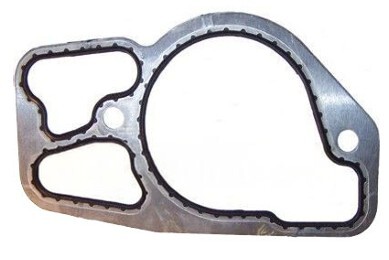
2B. Install the pump to the engine cover using a new HPOP engine cover gasket. Install the drive gear onto the HPOP shaft. There is no keyway.
3B. Torque the two HPOP mounting bolts to 18 lb-ft (24 Nm).
Caution: Confirm the drive gear is fully seated on the pump before installing the bolt and washer, or it may bind/slip and cause a no-oil-flow condition.
4B. Torque the drive gear bolt to 95 lb-ft (129 Nm). If the engine starts to rotate while tightening, the note says you don’t need to try to hold the engine; stopping at that point is stated to be sufficient.
5B. Apply RTV around the edge of the bolt cover plate and torque it to 8–10 lb-ft.
6B. Reinstall the upper reservoir gasket you removed unless it’s damaged or was leaking; replace if needed. A note warns there are three different reservoir gaskets—match the new gasket exactly to the old one to avoid cracking the lower reservoir area.
7B. Torque the top reservoir bolts to 18 lb-ft (24 Nm).
8B. Reinstall the IPR and the discharge hoses. Pull on the quick-connect hoses to ensure they are locked.
9B. Reinstall the fuel bowl using new fuel hard line sleeves.
10B. Refill the HPOP reservoir to within about 3/4 inch of the top. You may need to crank/turn the engine and recheck level a couple times as the pump refills.
11B. Purge the fuel bowl canister by turning the key to ON until the pump stops; repeat 2–3 times.
12B. Starting may take several attempts because the discharge hoses may have drained and now contain air. Do not crank more than 20 seconds at a time; allow the starter to cool between attempts.
13B. Once running, check for oil leaks at discharge hoses, front mounting gasket, reservoir gasket, and IPR.
14B. Check for fuel leaks at the four fuel hard line connections.
15B. It may take roughly 50 miles of hard driving to purge air from the oil rails and fuel rails introduced during service.


