
High Flow Fuel CVD Fitting - Full Step By Step How To Installation
Jan 9th 2026
Full Downloadable PDF Instructions Available Here: http://riffraffdiesel.com/content/RESOURCES/High%20Flow%20Fuel%20CVD%20Fitting%20Instructions.pdf
Parts Required: Riffraff Diesel High Flow Fuel CVD Fitting Set
Recommended Parts: Parker 60VLV-4 Viton Sleeve (1/4 inch); Gasoila® Diesel Soft-Set Thread Sealant
Recommended Tools: Standard Wrench set
1. Disconnect CAC inlet and outlet tubes from the intake spyder.
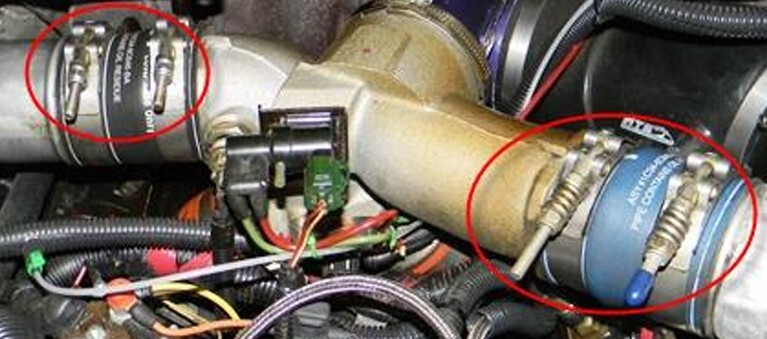
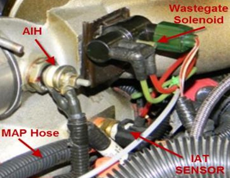
2. Disconnect the AIH leads, IAT sensor connector, MAP & waste-gate pressure hoses, & remove the waste-gate solenoid from the spider. (label as required)
3. Remove the clamp at the aft flange of the spider connecting it to the turbo.
4. Loosen the upper clamps from the spider to the plenum.
5. Remove the spider by pulling it free from the plenum boots.
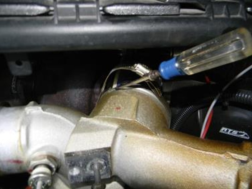
6. Locate the passenger side fuel line running from the fuel bowl along the head. It is a ¼” steel line that runs along the head and turns behind the head.
7. Using a 9/16” wrench, loosen the brass nut on the line and separate the line from the check valve. Remove the check valve from the head.
8. Install the Riffraff Diesel High Flow Fuel CVD into the head with the tapered threads into the head. A small amount of Gasoila is recommended on the tapered side only. Tighten, but do not over tighten the CVD fitting. Max torque is 60 -80 in-lb (5-7 ft-lb).
9. On the fuel line, you need to replace the Viton sleeve. The sleeve can be removed by using a pick or scribe to get it out. Replace with a new sleeve.
10. Install the fuel line onto the CVD fitting and tighten down to the point where there is no gap between the fuel line B-nut and the fitting.
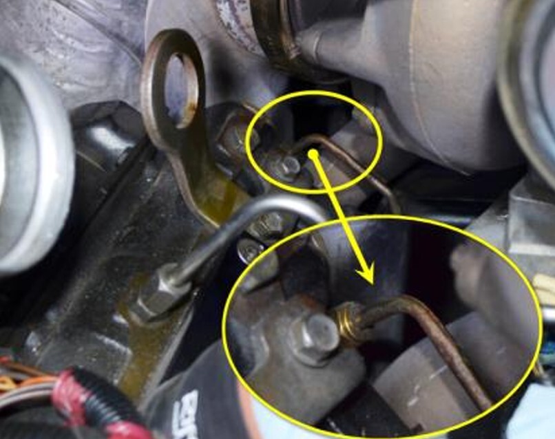
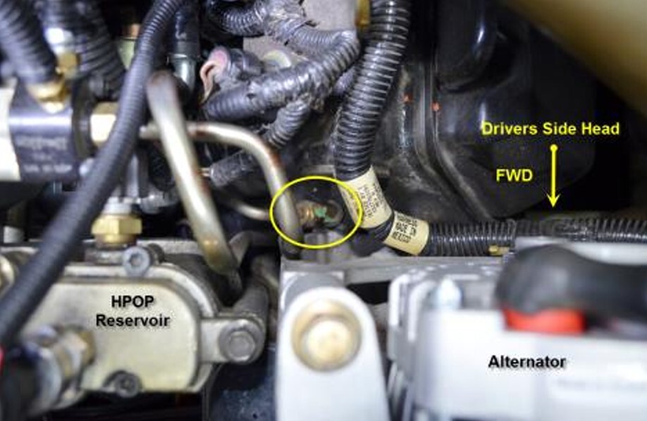
11. Locate the fuel line running from the fuel bowl to the drivers side head. The fitting is located just behind the alternator on the head at the forward side.
12. Using a 9/16” wrench, loosen the brass nut on the line and separate the line from the check valve. Remove the check valve from the head.
13. Install the Riffraff Diesel High Flow Fuel CVD into the head with the tapered threads into the head. Tighten, but do not over tighten the CVD fitting. Max torque is 60 -80 in-lb (5-7 ft-lb)
14. On the fuel line, you need to replace the Viton sleeve. The sleeve can be removed by using a pick or scribe to get it out. Replace with a new sleeve.
15. Install the fuel line onto the CVD fitting and tighten down to the point where there is no gap between the fuel line B-nut and the fitting.
16. Re-install the spider into the plenum boots. You will be required to work one of the boots around the spider flange. Using a flat blade screwdriver or cotter pin removal tool will help. Tighten the clamps down to secure the spider.
17. Align the turbo compressor housing with the spider flange making sure the o-ring stays in place. Align them by hand and then install the spider to turbo clamp. Do Not use the clamp to align the two parts.
18. Re-connect the AIH leads, IAT sensor connector, MAP & waste-gate pressure hoses, & install the waste-gate solenoid from the spider.
19. Align the drivers and passenger side CAC pipes with the spider and install the boots onto the spider. Tighten clamps to 60 in-lbs.
20. Turn the key on and off several times to pressurize the fuel bowl. Verify no leaks, then start the engine and re-check for leaks.
Pictures and instructions by Ken (Woodnthings on FTE)


