
Full Step By Step How To: 7.3L Powerstroke Stainless Steel Braided Fuel Line Kit
Sep 17th 2025
Full PDF Instructions can be downloaded here: https://www.riffraffdiesel.com/content/RESOURCES/Fuel%20Line%20SS%20Braided%20Hose%20Kit%20-%207.3L%2099-03.pdf
Product Link: https://www.riffraffdiesel.com/fuel-feed-line-ss-braided-hose-kit-7-3l-99-03/
IMPORTANT: Before starting installation, please be sure that all items supplied with the kit are accounted for.
Parts Required:
Riffraff Diesel Fuel Line SS Braided Hose Kit: Part# RDP-FFL-SD
Recommended Tools:
Various wrenches and hand tools
Instructions:
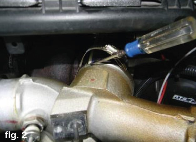
1. Drain the fuel bowl using the yellow drain lever on the rear of the bowl.
2. Disconnect the ground cables from both batteries.
3. Remove the clamps and boots from the CAC hot and cold side tubes.
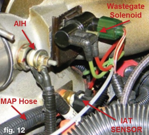
4. Remove the intake spider components. Start by removing the bolt holding the wastegate solenoid using an 8mm socket.
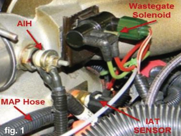
5. Remove the MAP sensor hose from the spider.
6. Remove the AIH power wire (if installed).
7. Remove the connector from the IAT Sensor.
8. Remove the upper clamps from the spider to plenum boots.
9. Remove the turbo to spider clamp. You may need to pry the clamp with a small screwdriver to get it to release from the groove.
10. Remove the intake spider by pulling forward to disengage from the turbo, then pull up to remove the spider from the boots.
11. Loosen the three (3) 13mm nuts from the GPR/AIH Relay bracket. This will allow the slotted bracket to be lifted out of the way and held to the side.
12. Remove the head fuel feed lines from the fuel bowl using a 9/16” wrench.
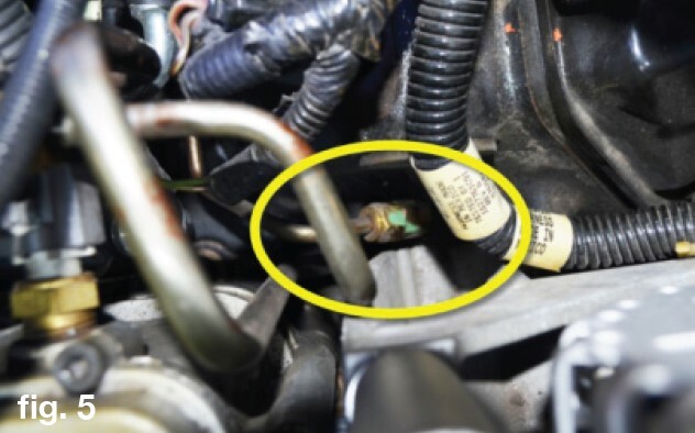
13. On the rear passenger side head plenum, remove the clamp holding the fuel line. Re-install the nut.
14. Using a 9/16” wrench, remove the feed line from the check valve. You will now be able to remove the line from the engine by feeding it forward around the turbo pedestal.
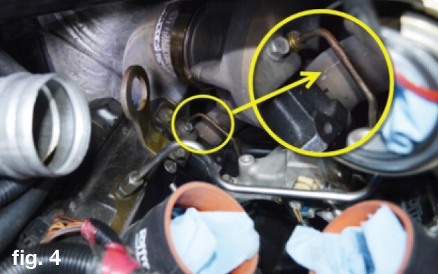
15. Remove the check valve from the head.
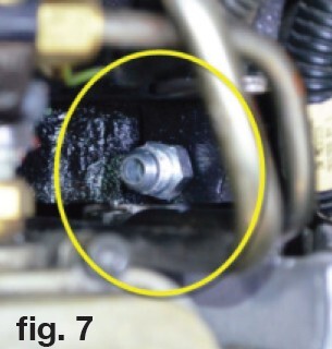
16. At the front of the drivers side head, remove the fuel line from the check valve using a 9/16” wrench.
17. Remove the drivers side head check valve.
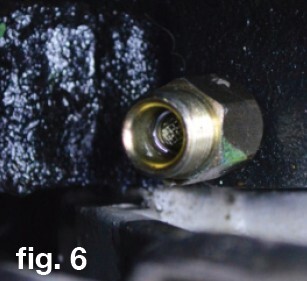
18. Using the provided Gasoila® thread sealant, apply a small amount to two of the straight adapters provided. Apply the sealant to the tapered thread portion only, not the flared side. Thread in the straight fittings into the head where the check valves were removed. DO NOT over torque.
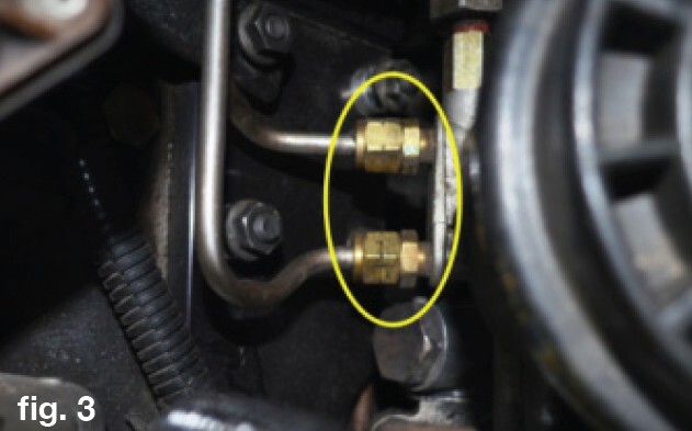
19. Remove the brass fuel line adapters from the passenger side of the fuel bowl.
20. Locate one of the 90º fittings from the kit. Apply Gasoila® thread sealant to the tapered threads. Thread the fitting into the forward bore of the fuel bowl. CAUTION: OVER TIGHTENING CAN CRACK THE FUEL BOWL! Thread the fitting by hand, then tighten it only enough to get the fitting to point back and up as shown.
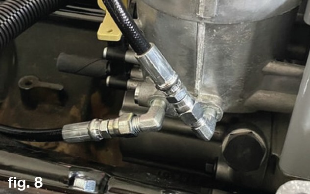
21. Locate the other 90º fitting from the kit. Apply Gasoila® thread sealant to the tapered threads. Thread the fitting into the rear bore of the fuel bowl. CAUTION: OVER TIGHTENING CAN CRACK THE FUEL BOWL! Thread the fitting by hand, then tighten it no more than half of a turn. Align fittings as shown above.
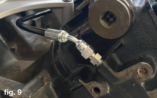
22. Route the shorter of the two (2) hoses from the forward fuel bowl fitting over the HPOP reservoir and down to the fitting installed in the driver’s side head. The hose end with the straight fitting will fasten to the fuel bowl fitting, while the 45º fitting will fasten to the driver’s side head.
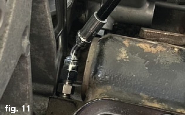
23. Route the longer of the two (2) hoses beneath the turbo pedestal to the rear of the passenger’s side head. The end with the 45º fitting will fasten to the head.
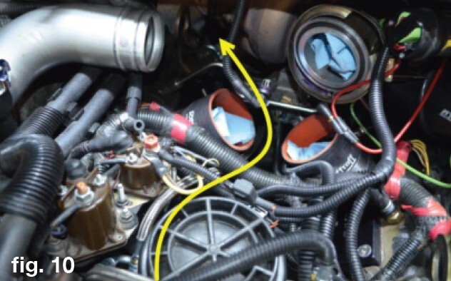
24. Route the hose forward below the turbo pedestal and between the passenger side HPOP hose and engine harness. Continue to route the hose to the fuel bowl and install onto the aft 90º fitting.
25. Install the GPR/MAIH Relay bracket back onto the studs and tighten the nuts.
26. Now that all the components are located, carefully tighten the nuts on the hoses using an 9/16” wrench. Tighten the hoses 1/4-1/2 turn from hand tight. Be careful to make sure you have clearance on the hoses and fittings before final torque.
27. Secure the RDP Hoses to make sure they do not rub on anything.
28. Close the fuel bowl drain valve.
29. Connect the ground cables back on the batteries.
30. Turn the key on without starting the engine. Cycle the key 3-4 times using a 20-30 second time to allow the fuel bowl to refill and pressure to build. Verify the connections with each key cycle to check for leaks. After the last cycle, the fuel bowl should be fully pressurized.
31. After verifying no leaks, re-install the spider and components.
32. Install the intake spider components.
33. Install the MAP sense hose from the spider.
34. Install the AIH power wire (if installed)
35. Install the connector from the IAT Sensor.
36. Install the upper clamps from the spider to plenum boots.
37. Install the turbo to spider clamp.
38. Re-install the CAC tube boots and clamps.
39. Verify all connections and test drive the truck. Check the fuel lines and fittings to ensure no leaks.
***Disclaimer: The information provided on this blog is for informational purposes only. We share our knowledge and experience, but we are not liable for any damages, injuries, or losses that may occur as a result of using this information. Situations are rarely cut and dry in the automotive world. Your situation will likely be somewhat different than what we describe here. Use your best judgment and always consult a qualified professional for automotive repairs and modifications. Your safety is your responsibility.


