
Ford 7.3 Powerstroke GTP38 Turbocharger Rebuild: How To
Aug 6th 2025
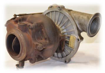
Believe it or not, rebuilding turbochargers is fairly easy and can be done with simple tools. We'll show you how, on a GTP38 turbo used in the 7.3 Powerstroke trucks from 1999.5 to 2003. These instructions will be similar for other year 7.3's.
Full PDF Instructions can be downloaded here:99.5-03 GTP38 360OBearing Turbo Rebuild Instructions
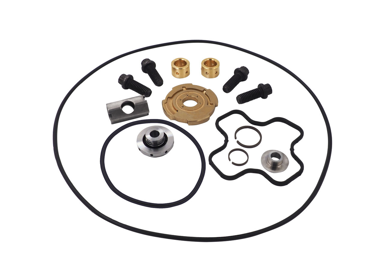
IMPORTANT: Before starting installation, please be sure that all items that were supplied with the kits are accounted for.
Required Parts:
- GTP38 Rebuild Kit 360 Bearing: https://www.riffraffdiesel.com/gtp38-360-bearing-rebuild-kit-99-03/
- GTP38 Compressor Housing O-ring: https://www.riffraffdiesel.com/garrett-compressor-housing-o-ring-99-5-03/
- GTP38 12 pt. Housing Bolts: https://www.riffraffdiesel.com/garrett-12pt-replacement-turbo-housing-outlet-bolt-set/
Recommended Tools:
- GTP38 Rebuild Kit GTP38 360oBearing Kit
- 8 mm 12pt wrenches and sockets
- Locking Pliers
- 16mm or 5/8” wrench
- Scotch Brite® Pad
- PB Blaster®
- Brake Cleaner or Equivalent
- Clean Motor Oil
Instructions:
1. Thoroughly clean the turbo assembly of grime and buildup. Soaking the exposed bolts with a penetrating oil like PB Blaster® will help in disassembly.
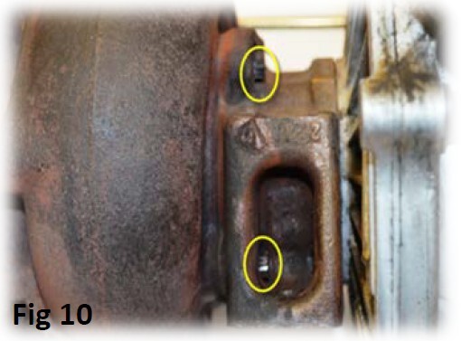
2. Using an 8mm 12pt wrench, break the torque on all of the exposed bolts. You may find that using a hammer to strike the wrench will be the easiest method to initially loosen the bolts. NOTE: You may find the turbo housing to center carrier mounting bolts (4) loose or missing. This is a known problem covered by TSB 03-14-09. Replacement bolts are included in your kit.
3. You can make reference marks on the parts before disassembly to make reinstallation easier. It is not required as the parts only fit one way.
4. Remove the wastegate actuator from the compressor housing by removing the two 10mm nuts and the “E” Clip from the wastegate lever.
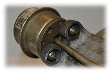
5. Remove the actuator and set aside for re-installation.
6. Remove the (7) bolts from the EBPV housing to turbine housing.
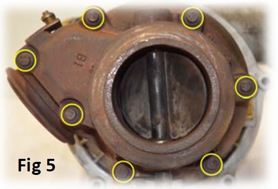
7. Tap the housing with a soft mallet to loosen it up and allow it to be removed. Remove the EBPV housing and set aside.
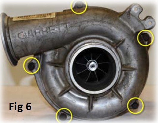
8. Remove the (5) bolts from the compressor housing and remove the compressor housing. You may need to tap on the housing with a soft mallet to loosen it up. Use caution when removing the housing to protect the compressor wheel fins.
9. Using a pair of locking pliers, firmly clamp the pliers onto the turbine wheel hub. You can use a screwdriver through the locking pliers as a lever to hold them securely.
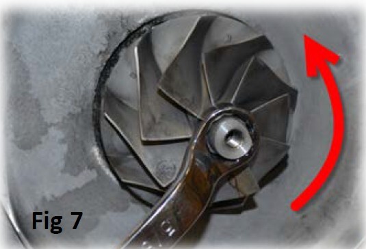
10. Using a 16mm or 5/8” wrench and the pliers on the turbine wheel, loosen the compressor wheel by turning it counter clockwise off of the shaft.
11. Remove the (4) bolts holding the compressor housing back plate onto to the center carrier.

12. Lift the back plate off of the turbo shaft. The thrust bearing and collar may lift off with the back plate or may stay on the shaft. Just be careful to take note on their orientation for reinstallation.
13. Remove the (4) bolts from the center carrier to the turbine housing, Tap on the turbine housing with a soft mallet and you should be able to free the housing from the center carrier. This will expose the turbine wheel, be careful not to damage the wheel.
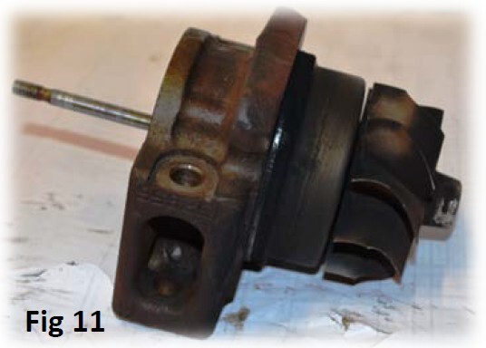
14. While supporting the center support, lightly tap the exposed shaft where the compressor wheel was removed. The turbine wheel and shaft assembly will come out of the center carrier fairly easily.
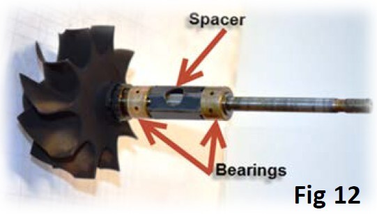
15. Once removed, slide the bearings and spacer off of the shaft.
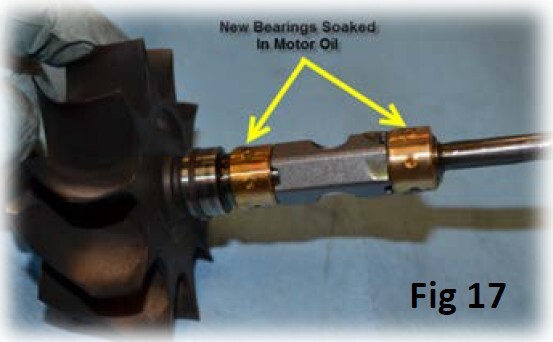
16. Open the rebuild kit and remove the (2) Journal Bearings, Thrust Washer and Thrust Bearing. Soak them in a cup of clean motor oil before installation.
17. Remove the oil seal ring from the turbine wheel shaft assembly. You can use a small pick or scribe to remove the seal from the shaft groove. Discard the seal.
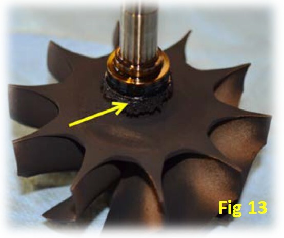
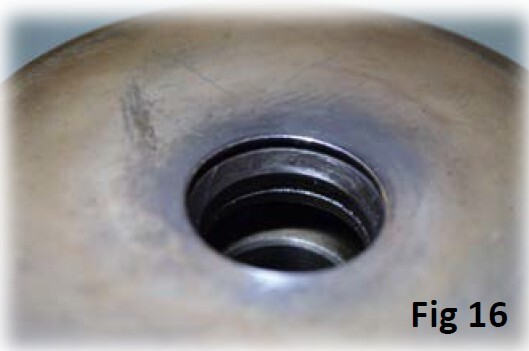
18. Clean the built up oil (coked oil) from the turbine shaft. You can carefully scrape the bulk of it away, using a small wire brush will remove the remaining debris from the shaft. You can then polish the shaft area with a piece of Scotch Brite® to final clean/prep it.
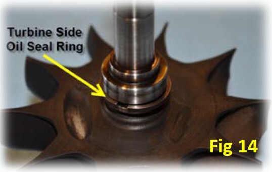
19. After the shaft is clean, you can get the new seal ring from the kit. It is the larger of the two seal rings. Slide it over the shaft and work it onto the groove in the shaft. Be careful not to spread it too wide while installing it. (Fig 14)
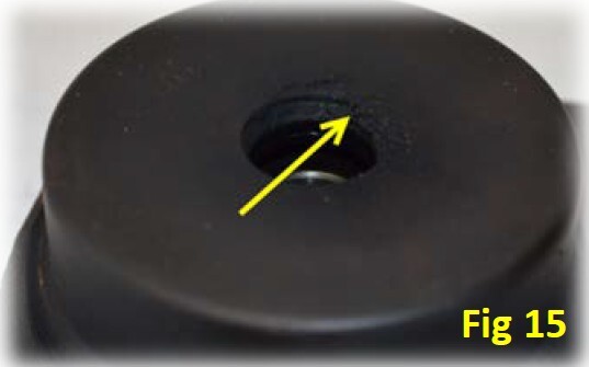
20. On the center cartridge you will need to clean the oil seal ring mating groove. Carefully remove the built up debris using a small wire brush and Scotch Brite® as required. Brake cleaner or similar solvent will allow you to flush the cartridge of all debris. Follow with compressed air and sit the center cartridge aside.
21. Take the (2) Journal Bearings out of the oil and place them on the turbine wheel shaft assembly along with the spacer as shown.
22. Insert the turbine shaft assembly into center cartridge. Once you get to the point where the shaft seal ring engages into the center cartridge, you will need to press it firmly until you feel a slight click. This will ensure the seal ring is firmly engaged in the center cartridge.
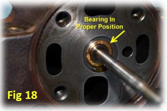
23. Verify the journal bearing is correctly positioned in the center cartridge.
24. Place the turbine housing onto the center cartridge and install using the (4) new bolts included in the kit. Tighten the bolts 15-17 ft-lbs in a crisscross pattern.
25. Remove the thrust bearing and washer from the oil and install the oil seal ring onto the bearing groove.

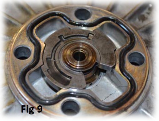
26. The Thrust Bearing is installed as shown.
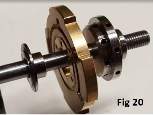
27. Install the thrust bearing into the compressor backplate. It can only be seated in one position. The oil seal ring will click into the backplate when pressed firmly.
28. Install the Thrust Bearing Plate with the oil grooves towards the center section.
29. Install the thrust bearing hat into the plate (it will fit loosely). The oil (or grease if necessary) will hold it into position for assembly.
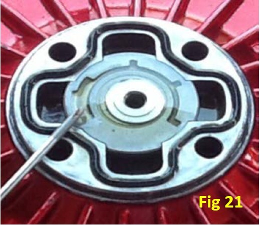
30. Install the backplate to center cartridge seal into the groove on the backplate. A small dab of petroleum jelly or RTV may be needed to hold it in place. Use only as needed.
31. Keeping the Thrust Bearing seated in the compressor backplate, assemble the backplate onto the center cartridge over the exposed shaft and align the bolt holes. They will only align in one position.
32. Tighten the (4) bolts 15-17 ft-lbs in a crisscross pattern.
33. Install the compressor wheel onto the shaft. Turn it by hand while holding the turbine wheel firmly. Tighten the wheel to a torque of 10 ft-lbs.
34. Replace the compressor housing to backplate O-ring seal if it is damaged.
35. Carefully install the compressor housing onto the backplate. Make sure you seat it down evenly.
36. Install and tighten the (5) bolts 15-17 ft-lbs using a crisscross pattern to ensure the housing is evenly seated onto the backplate.
37. Install the (7) bolts into the EBPV housing and tighten 15-17 ft-lbs.
38. Install the wastegate actuator onto the turbo. Tighten the nuts 50-70 in-lbs.
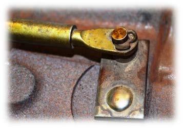
39. Insert the wastegate actuator rod end over the pin on the wastegate lever. Install the E-Clip until it is seated fully in the groove.
Instructions and pictures provided by Ken
(Woodnthings on FTE)


