
Electrical Sensor 101 - The 7.3's Sensors and How They Work
Posted by Adam Blattenberg on Jan 6th 2026
Electrical for many can be scary. Fear of the unknown is the real issue. So let's get one unknown out of the way. Sensors. Luckily for 7.3 owners, there aren’t a ton of sensors, especially compared to more modern era diesels. The 7.3 has 8 to 10 different sensors, depending on year and package, and those sensors are fairly simple in how they work. Here’s a very quick and very simple breakdown of each sensor type found on the 7.3 Powerstroke and how they work. Electrical engineering is very technical so we’re going to make a bunch of comparisons to make understanding how they work much easier. If you’re actually an electrical engineer who likes everything to be technical, we’re very sorry. As much as some of our comparisons may help the majority of us shade-tree mechanics understand how these sensors work, we're leaving out all the heavy technical stuff.
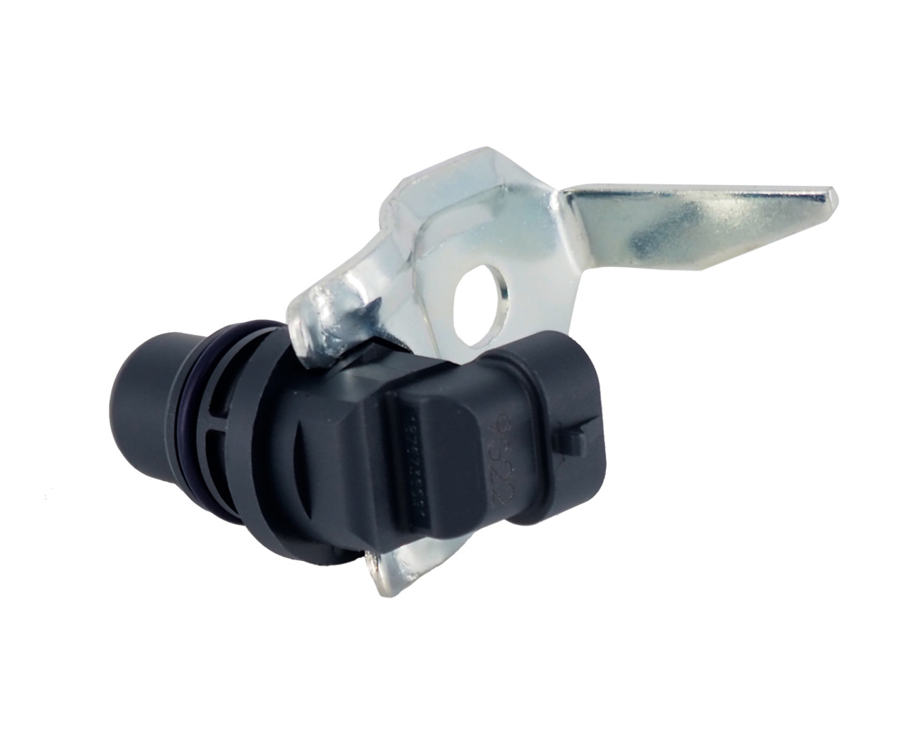
1. Hall-effect sensors
Used in one sensor:
Cam Position Sensor / CPS (also known as a CMP)
How it works:
Think of it like a magnetic on/off switch. Inside are electronics that sense a magnetic field. As the engine spins, a metal target (called the “tone wheel” or “tone ring”) passes the sensor tip. That tone ring has high and low spots, so each time it passes the sensor, the magnetic field changes, and when it does, the sensor emits a small amount of voltage (the voltage is either “on” or “off”). The PCM then uses this info to understand where the camshaft is in its rotational cycle
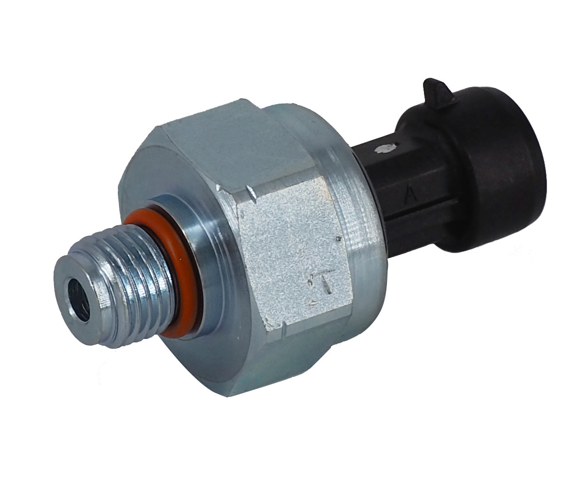
2. Variable-capacitance pressure sensors
Used in these sensors:
ICP = high-pressure oil system pressure (HEUI control)
EBP = exhaust back pressure (turbo control strategy)
MAP/Boost = intake pressure
BARO = outside air pressure (often inside the PCM)
How it works:
Think of it like a tiny pressure “drum skin” that moves. Pressure pushes on a very thin metal diaphragm (drum skin) inside the sensor. When it flexes (as voltage flows through it), its ability to store electricity is changed. The sensor’s built-in electronics can turn that sensed change into a signal the PCM can read. The PCM then uses this data for many things, such as: fueling, turbo control, altitude correction (for air density and fuel flow), and diagnostics.
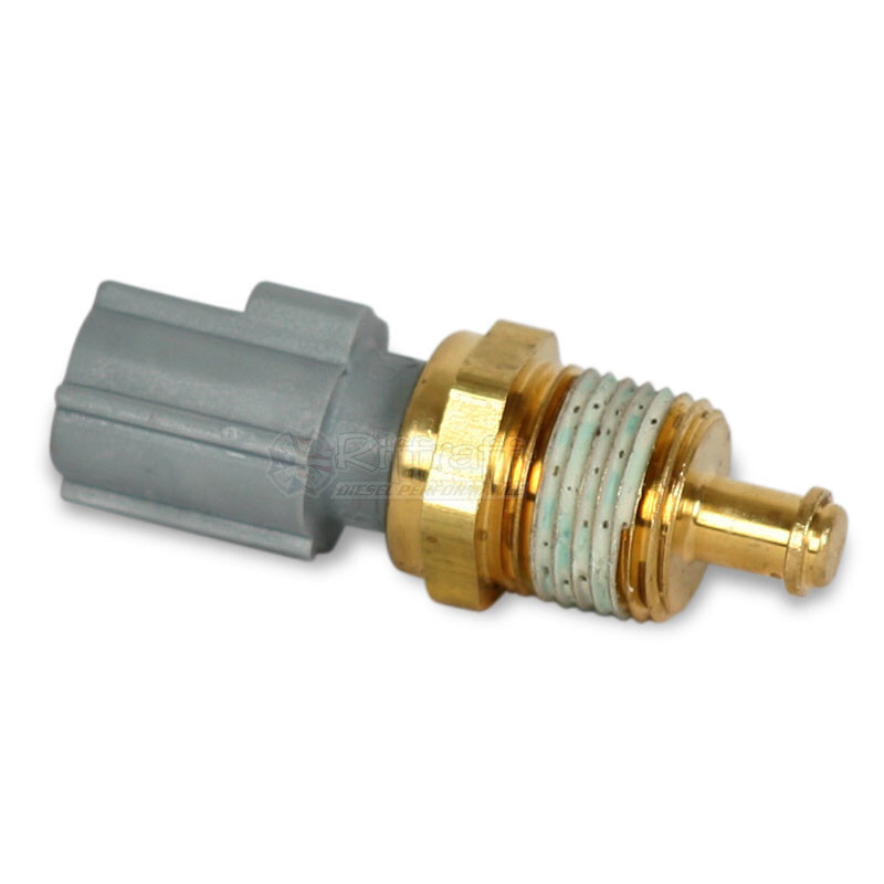
3. Thermistor temp sensors
Used in these sensors:
ECT = engine coolant temp
EOT = engine oil temp
IAT = intake air temp
MAT = charge/manifold air temp (varies by platform/year)
How it works:
Think of it as a piece of metal whose resistance changes with temperature (cause that’s exactly what it is). As temperature changes, the sensor’s resistance changes, and therefore the voltage out of the sensor changes too. The PCM sends a small amount of voltage through the sensor, measures the change, and uses the data for many things such as: warm-up fueling, fan control, and protecting the engine (hot oil/coolant/air equals a change in fueling and other commanded behaviors).
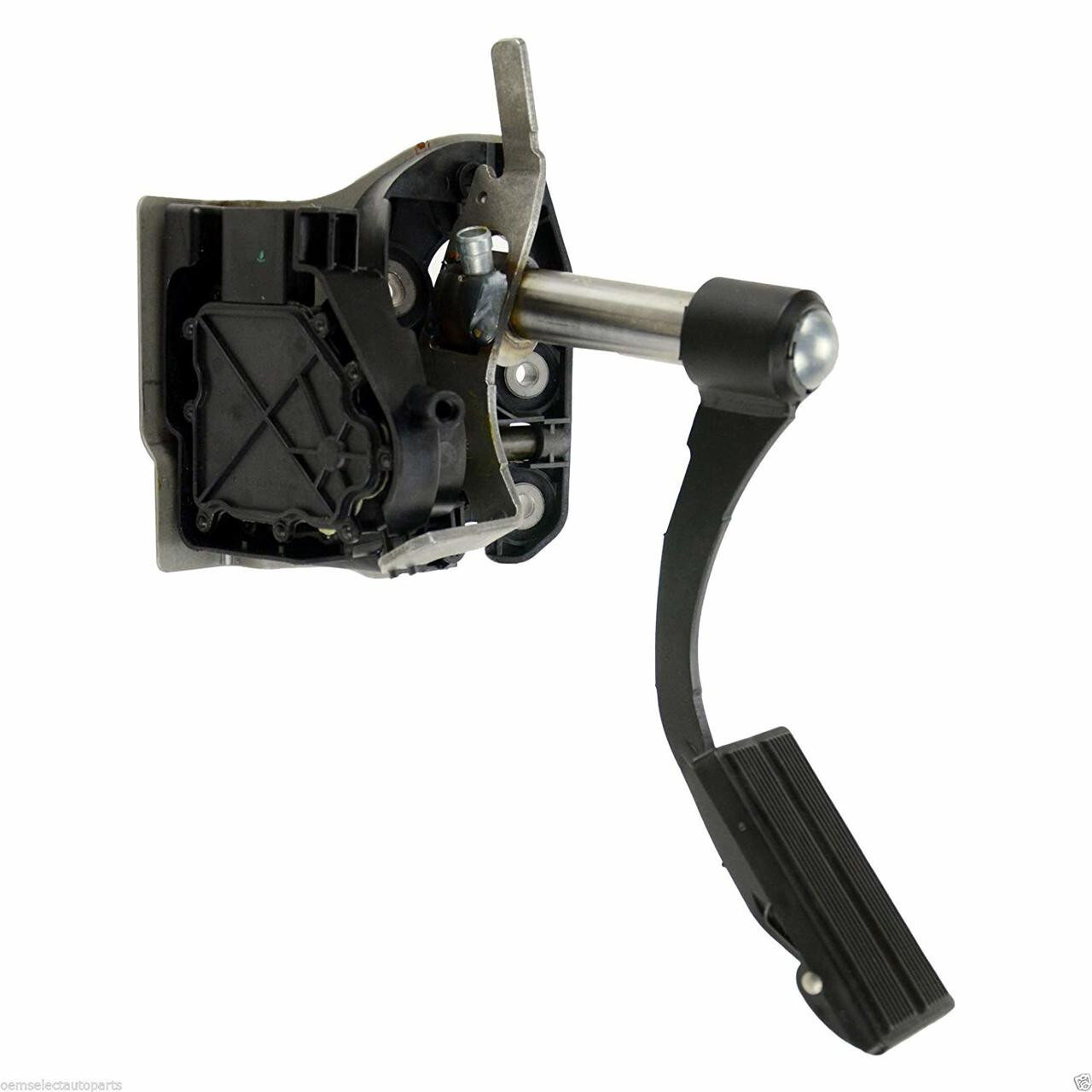
4. Potentiometer position sensors
Used in this sensor:
Accelerator Pedal / APPS
How it works:
Think of it like a volume knob where voltage changes the more you turn the knob. The sensor consists of a part that sends the voltage, and several others that accept it (or one with varying levels of resistance). As the pedal is pushed down, a “wiper” (supplied with a constant amount of voltage) slides over the different resistance areas. As the voltage comes out the other side, the PCM looks at the difference between input and output to determine throttle pedal position.
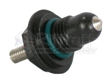
5. Conductivity “water in fuel” sensor
Used in this sensor:
Water In Fuel / WIF
How it works:
Think of it as water completing a circuit, just like those labels on hair dryers warn us about bathtubs, water can conduct voltage. The key here is that diesel doesn’t conduct electricity well. Water conducts way better. The sensor consists of two probes submersed in the fuel filter housing, under fuel. When enough water collects and bridges the sensor probes, it completes the circuit and the PCM/cluster turns on the WIF light, warning you to drain it before water damages the fuel system.
Super Quick Cheat Sheet:
Hall effect = magnetic on/off pulses
Capacitance pressure = pressure flexes diaphragm → PCM reads voltage or frequency
Thermistor = temp changes resistance → PCM reads voltage
Potentiometer = position changes voltage (like a knob)
Conductivity = water lets electricity flow → warning light


