
7.3L Powerstroke Injector Tear Down: What's Inside?
Posted by Adam Blattenberg on May 5th 2026
The 7.3 Powerstroke’s HEUI injection system relies on oil pressure to fire the injectors. Unlike most light duty diesel injection systems on the road today, where the pump (CP3, CP4, VE, VP, etc) creates the fuel pressure, the majority of the pressure for a 7.3L is created within the injector itself. This means the 7.3’s injectors are more complex than most others (or at least have more moving parts). In this blog we’ll be tearing down a 7.3L injector to see how it ticks.
One Big Note: Do NOT consider this a how to discussion. Keep in mind, we’re not injector rebuilders, and we’re not rebuilding this injector, there's too much body rust. This article will only be about what’s inside and how it works. Many of the methods of disassembly and parts handling used here should not be followed and we'll skip some parts when they don't help tell the injector's story (shims, sleeves, seals, etc). While many “shade tree mechanics” have successfully rebuilt their own injectors, we recommend relying on the pros for proper assembly and most importantly, flow testing.
Some Quick 7.3 HEUI Info Before We Start Teardown:
Simplified Operation: The IDM energizes the injector solenoid, the solenoid moves the poppet valve allowing high-pressure oil to “push” on the intensifier piston, and that piston drives the fuel plunger down which pushes the fuel into the nozzle, and the nozzle sprays that fuel into the cylinder. Bang, and it starts again.
Pressures: A typical 7.3 HEUI injector uses roughly a 7:1 intensifier ratio, so 3,000 psi oil (generally), can become about 21,000 psi fuel pressure at the nozzle. Fuel pressure supplied to the injectors is 50-65 psi, usually.
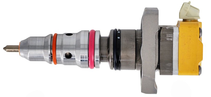
Split Injector: There are two sides to a 7.3 injector, fuel and oil. Fuel is towards the tip or bottom, oil is towards the top.
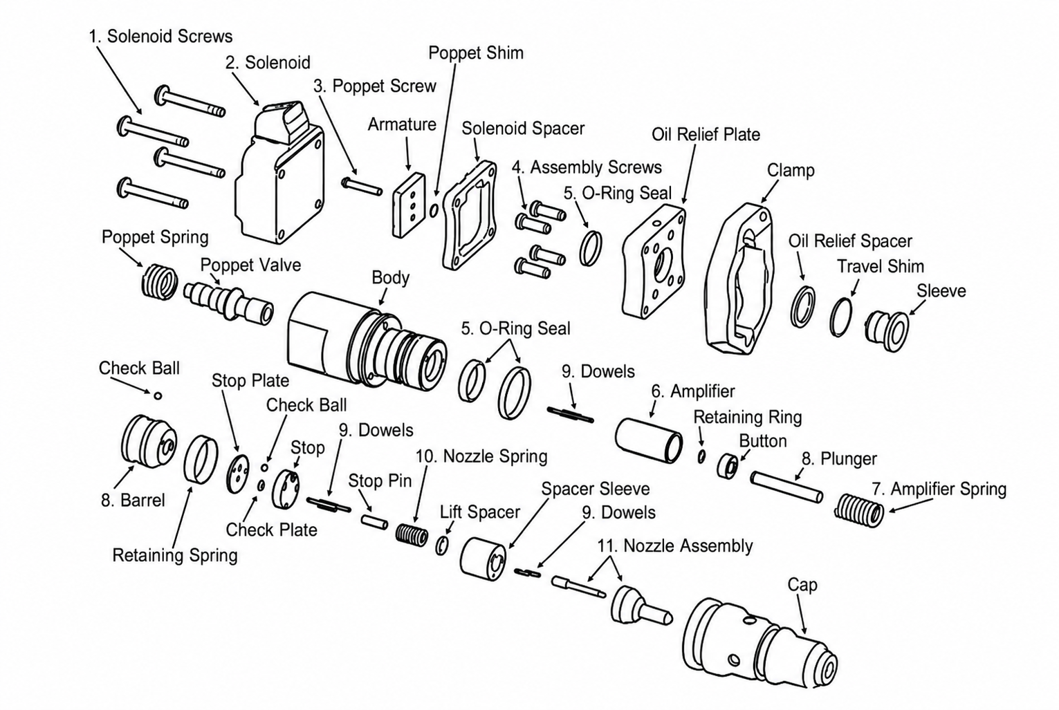
Note: Multiple names exist for the parts gone over here. We'll be using the names listed on this diagram, but calling out the other common names used when applicable.
Teardown: Starting at the top
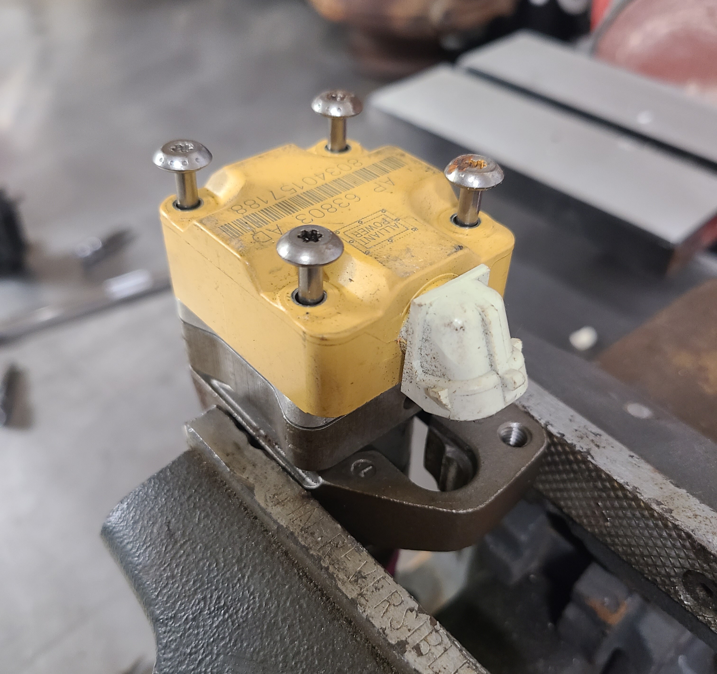
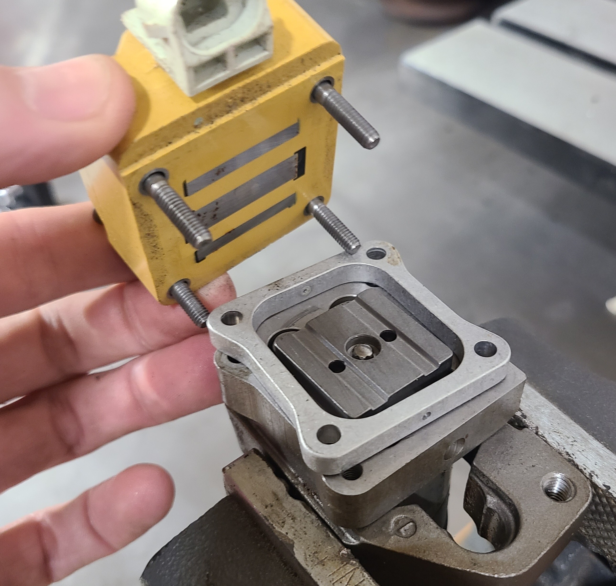
01-02 Solenoid: The Solenoid is held on with four specialty torx screws. It’s an electrical coil and when energized, it pulls the Armature Plate upwards, opening the Poppet Valve which starts everything in motion to begin an injection event. The spacer sets the air gap between the solenoid and armature. That gap matters because it controls how quickly and cleanly the injector reacts.
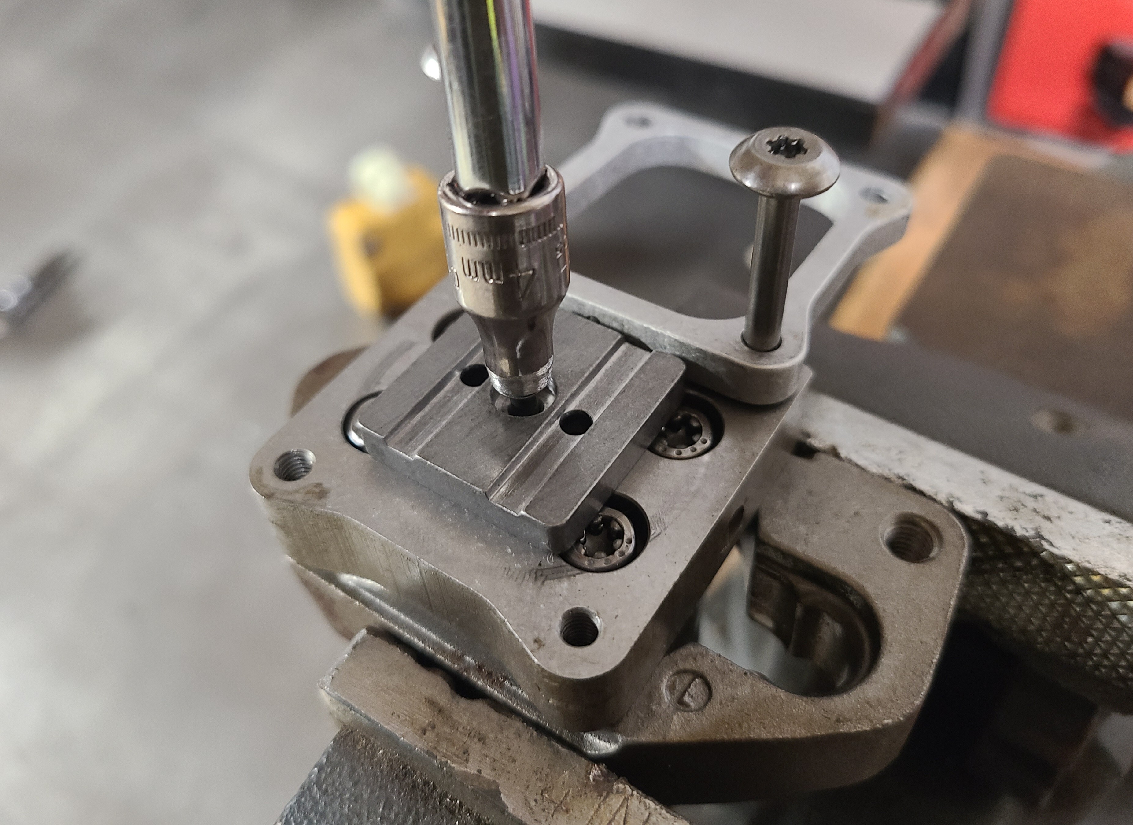
03 Armature Plate: The Armature Plate comes off with a specialty socket (although not recomended, a shaved down 4mm socket, like we used, can work). We used the Solenoid Spacer to hold it in place while removing the Poppet Screw. The Armature Plate is pulled magnetically by the Solenoid and transfers that movement to the Poppet Valve. If its clearance is off or the surface is worn, injector response gets lazy or inconsistent.
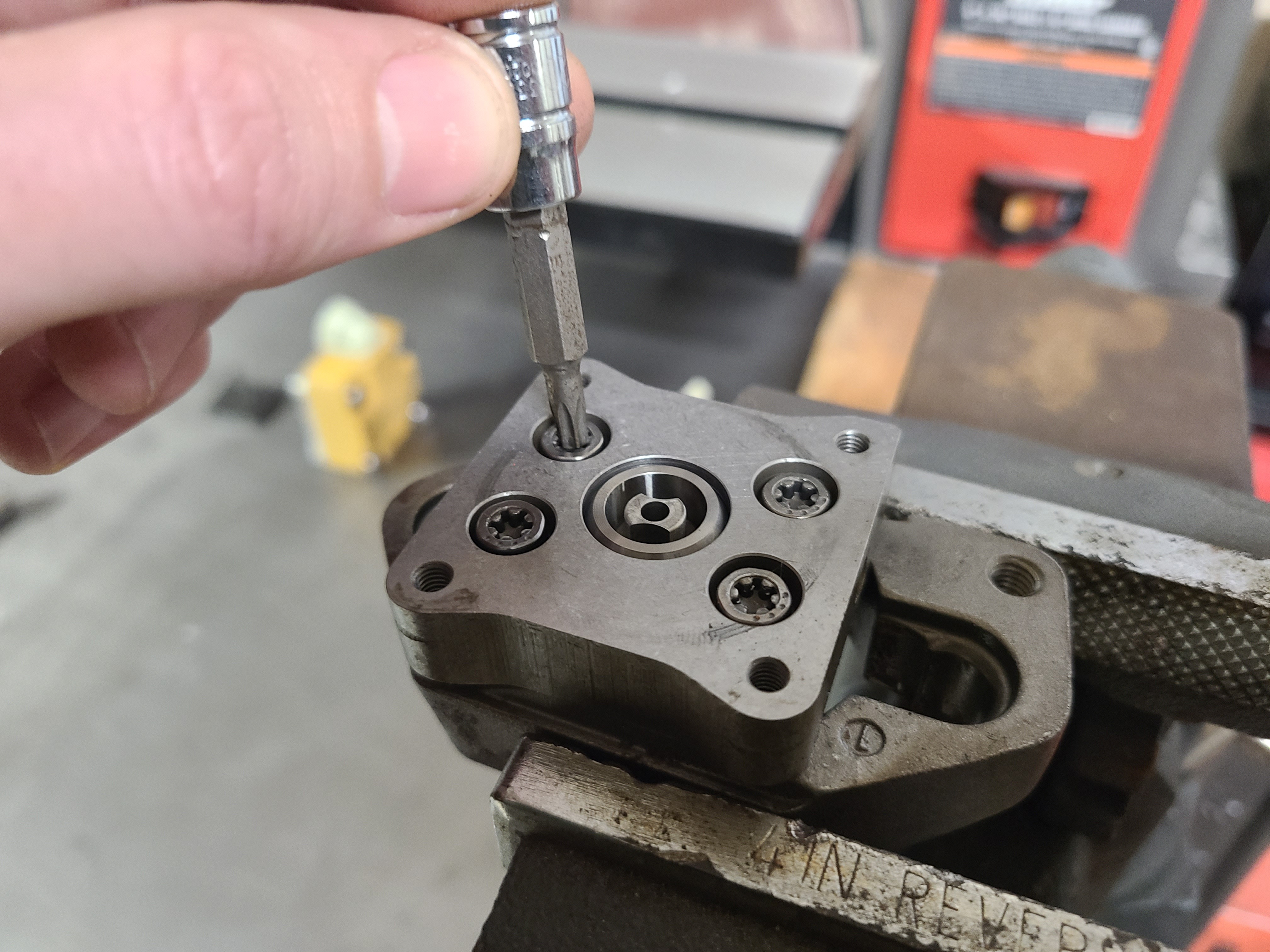
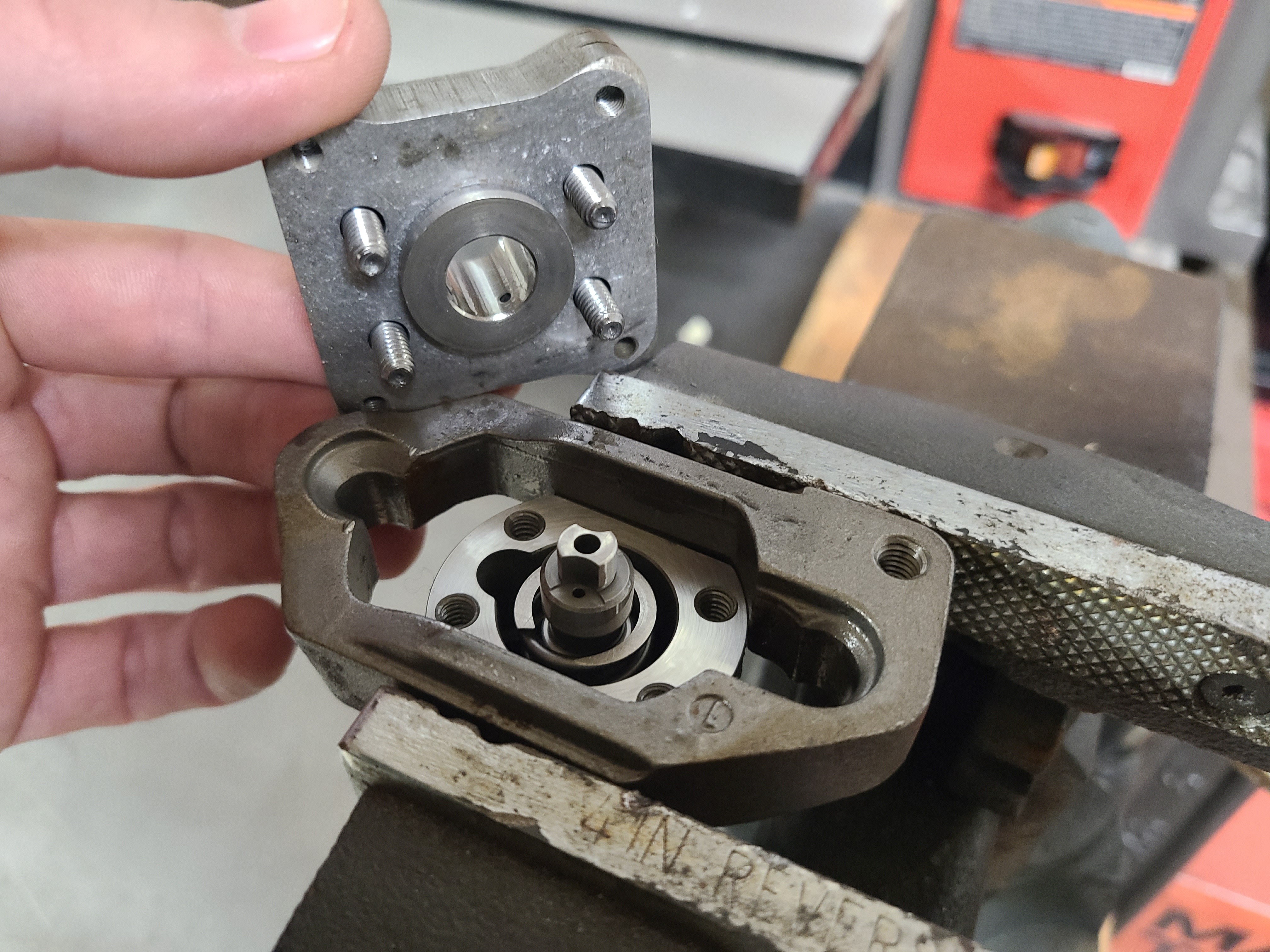
04-05 Oil Relief Plate: The Oil Relief Plate (aka Adapter Plate) is held on with four bolts. The Oil Relief Plate routes oil through the upper injector and gives the internal seals a surface to work against. Scratches, debris, or poor sealing here can create internal oil leakage.
06-08 Poppet Valve and Spring: The Poppet Valve is the high-pressure oil gatekeeper. The Armature opens it, oil flows to the Amplifier, and injection begins. The Poppet Spring pushes the Poppet Valve back closed when the Solenoid shuts off. A weak spring can make the injector slow to end the injection event.
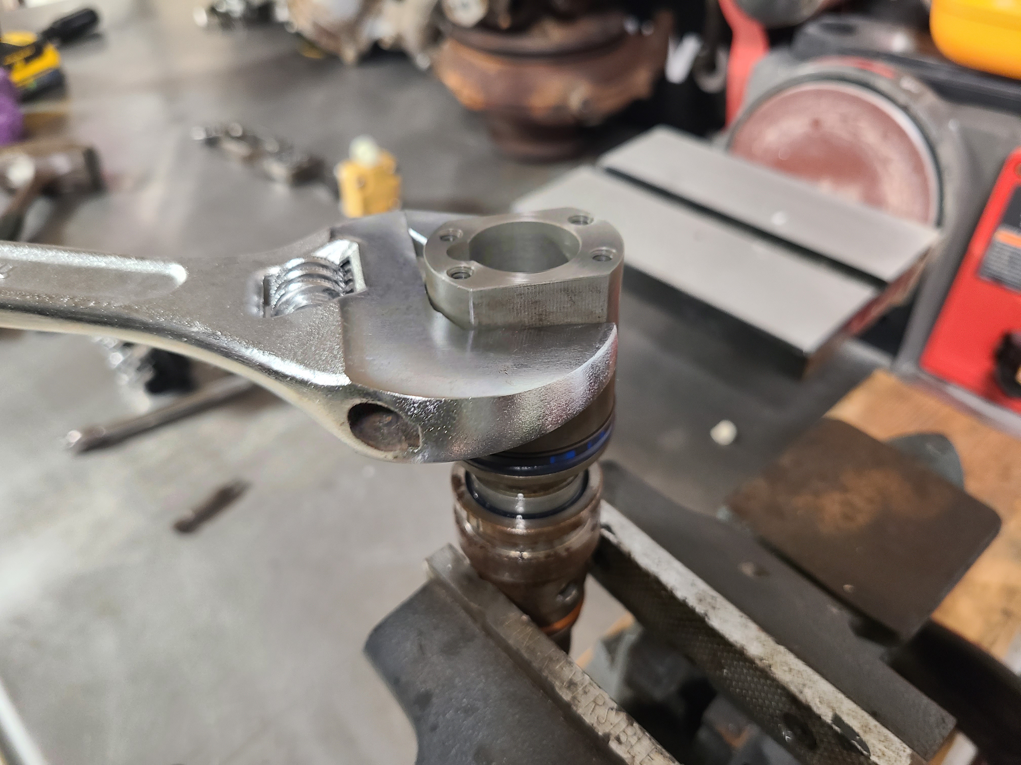
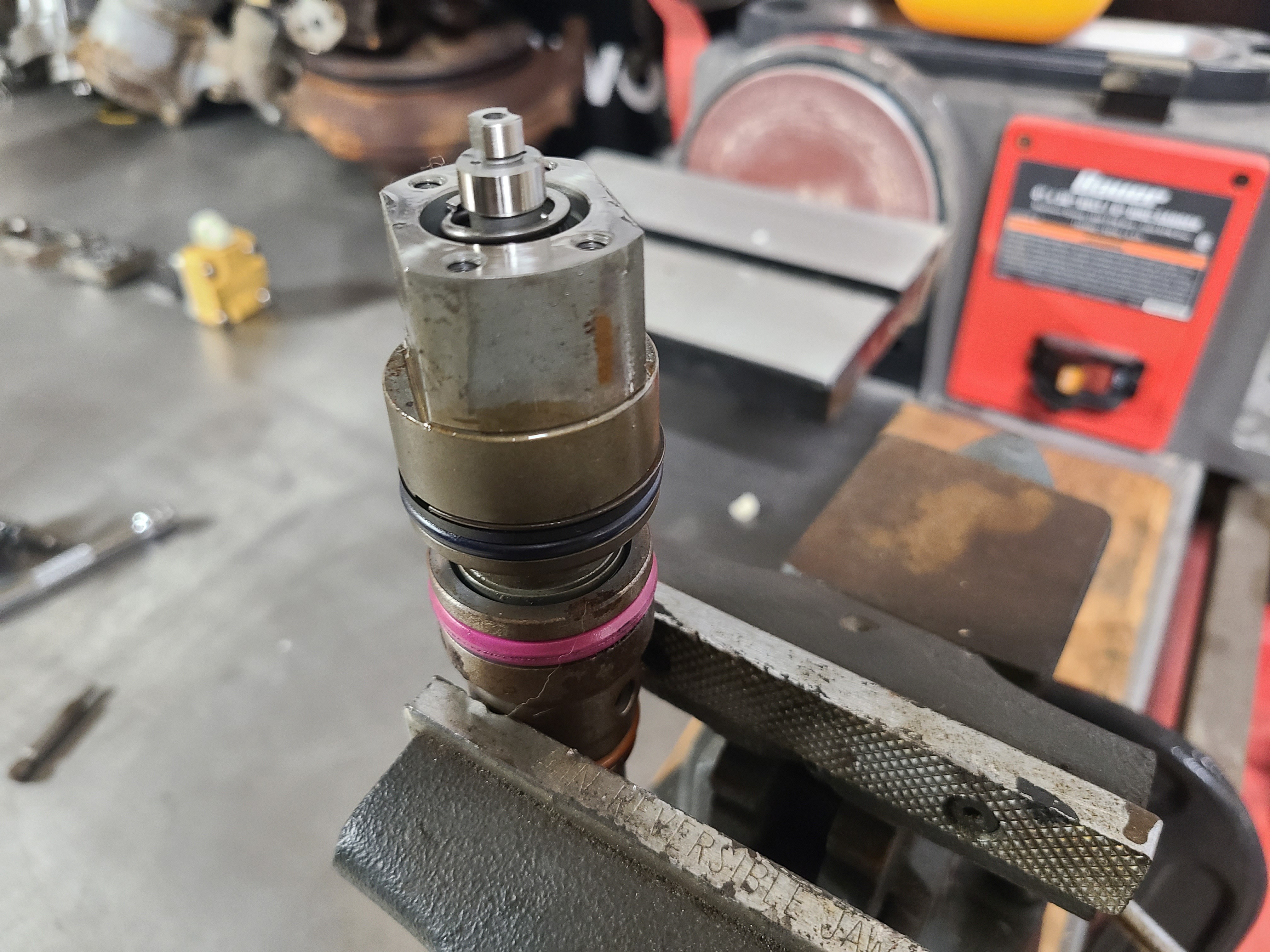
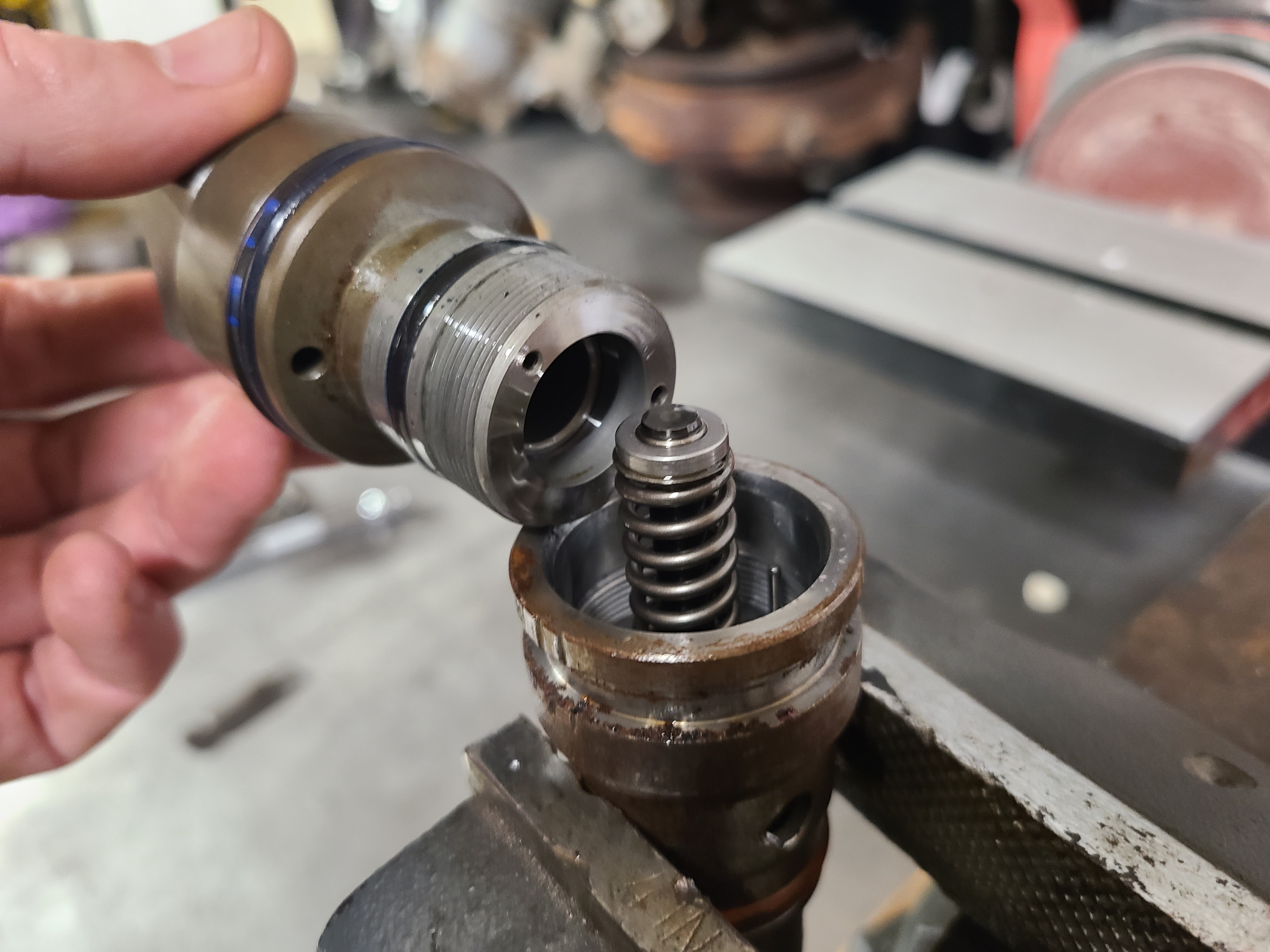
09 Body Separation: At this point the upper Oil Side body must be removed to access the fuel side, but first it must be removed to access the Amplifier (aka Intensifier). To avoid damage, specialty tools should be used to hold the injector (which we did not use) while seperating the two halves. The upper body unthreads from the lower with standard right hand threads. We used an adjustable wrench, although specialty tools are available, and are necessary during reassembly for accurate torque settings.
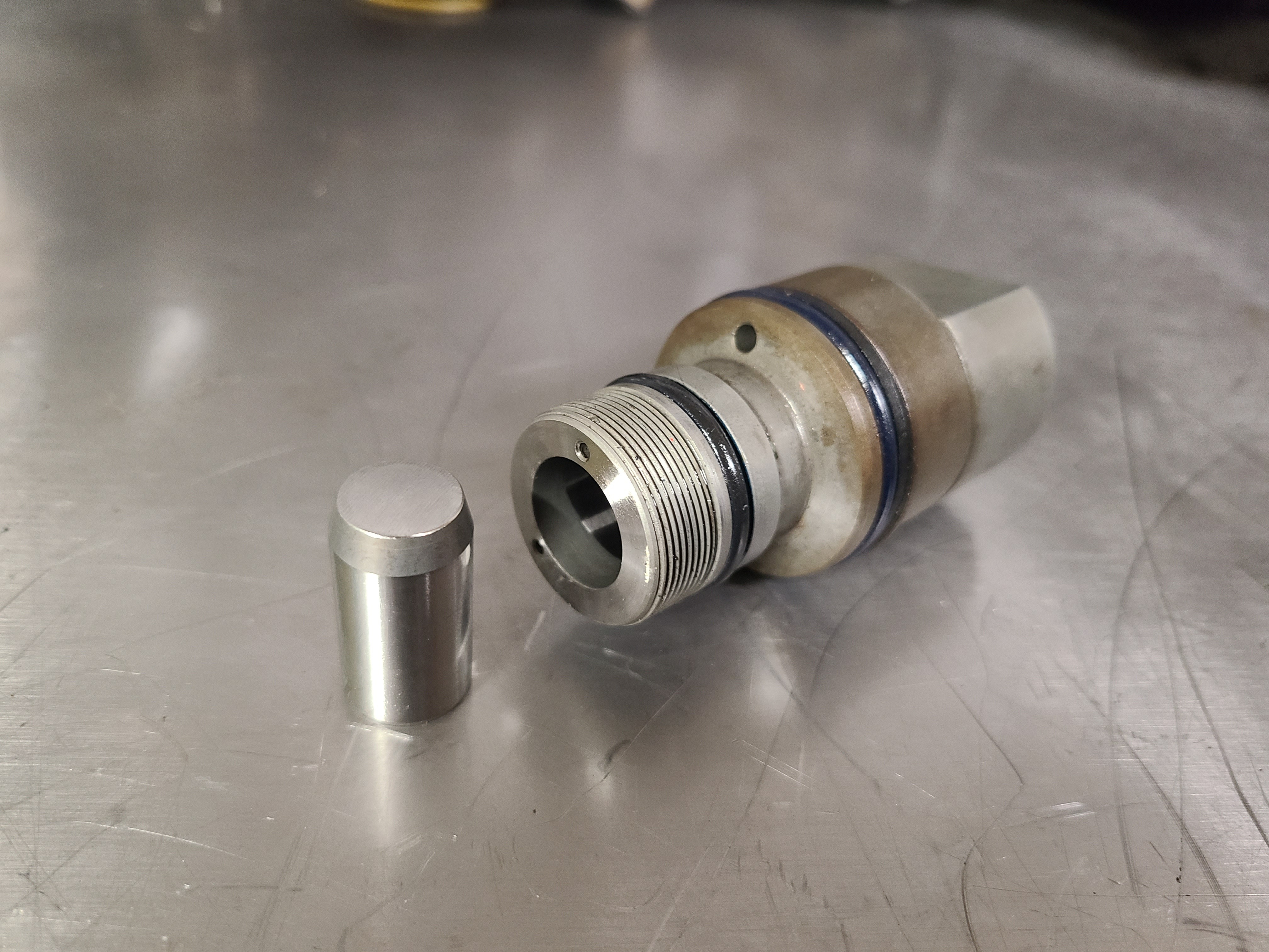
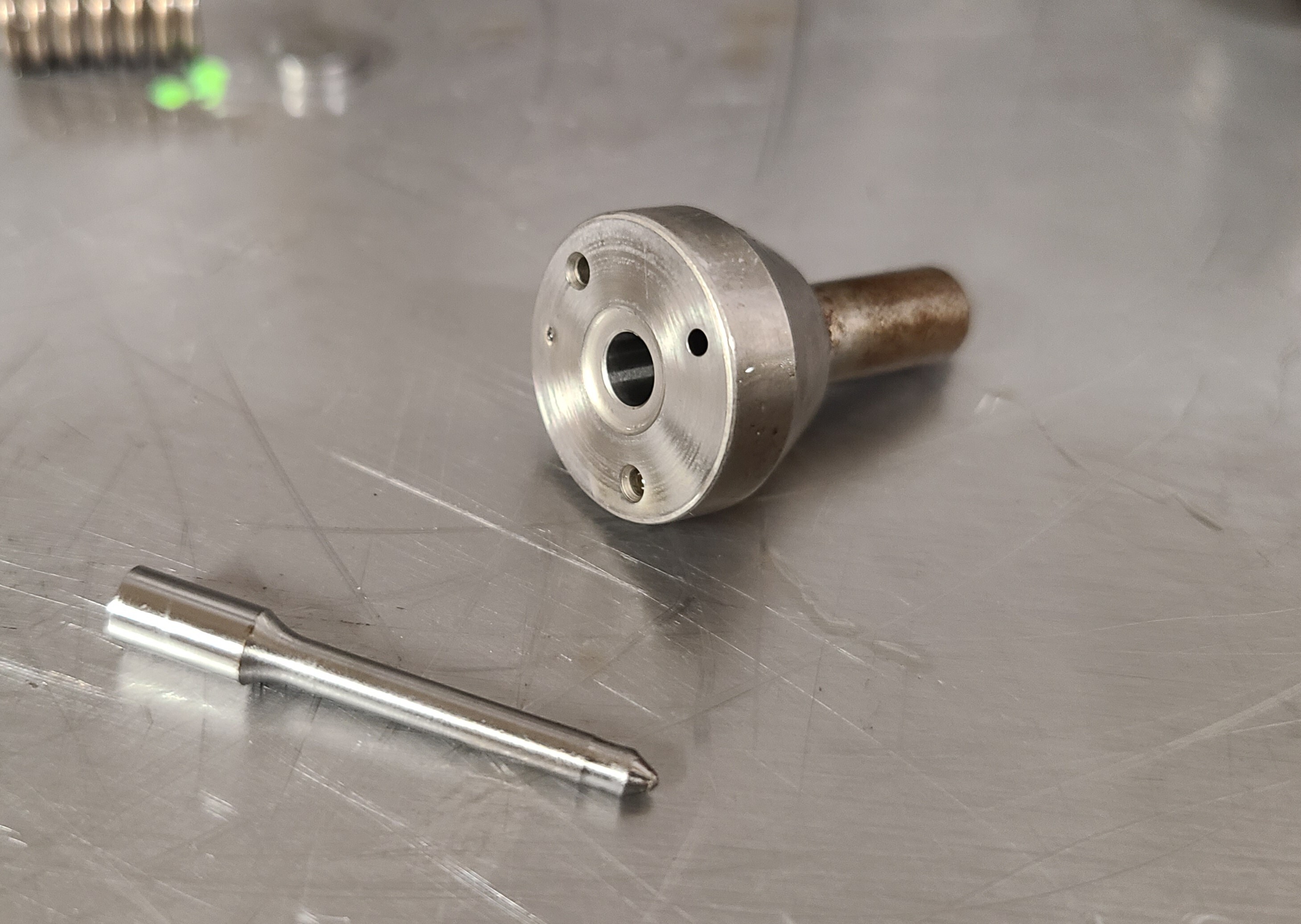
10 Amplifier (also called the Intensifier): Located inside the upper body, this is the Amplifier (piston on left). High-pressure oil pushes on the Amplifier, and the Amplifier drives the Plunger (aka fuel plunger, coming up next). This is the muscle that turns oil pressure into much higher fuel pressure.
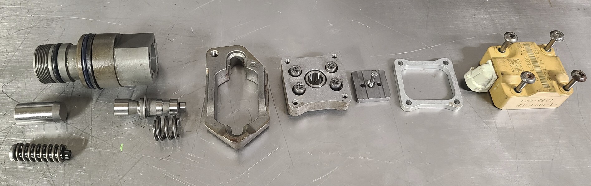
11 Oil Side Parts Laid Out: Here's all the oil side parts laid out in order. From here on we'll be working on the fuel side of the injector.
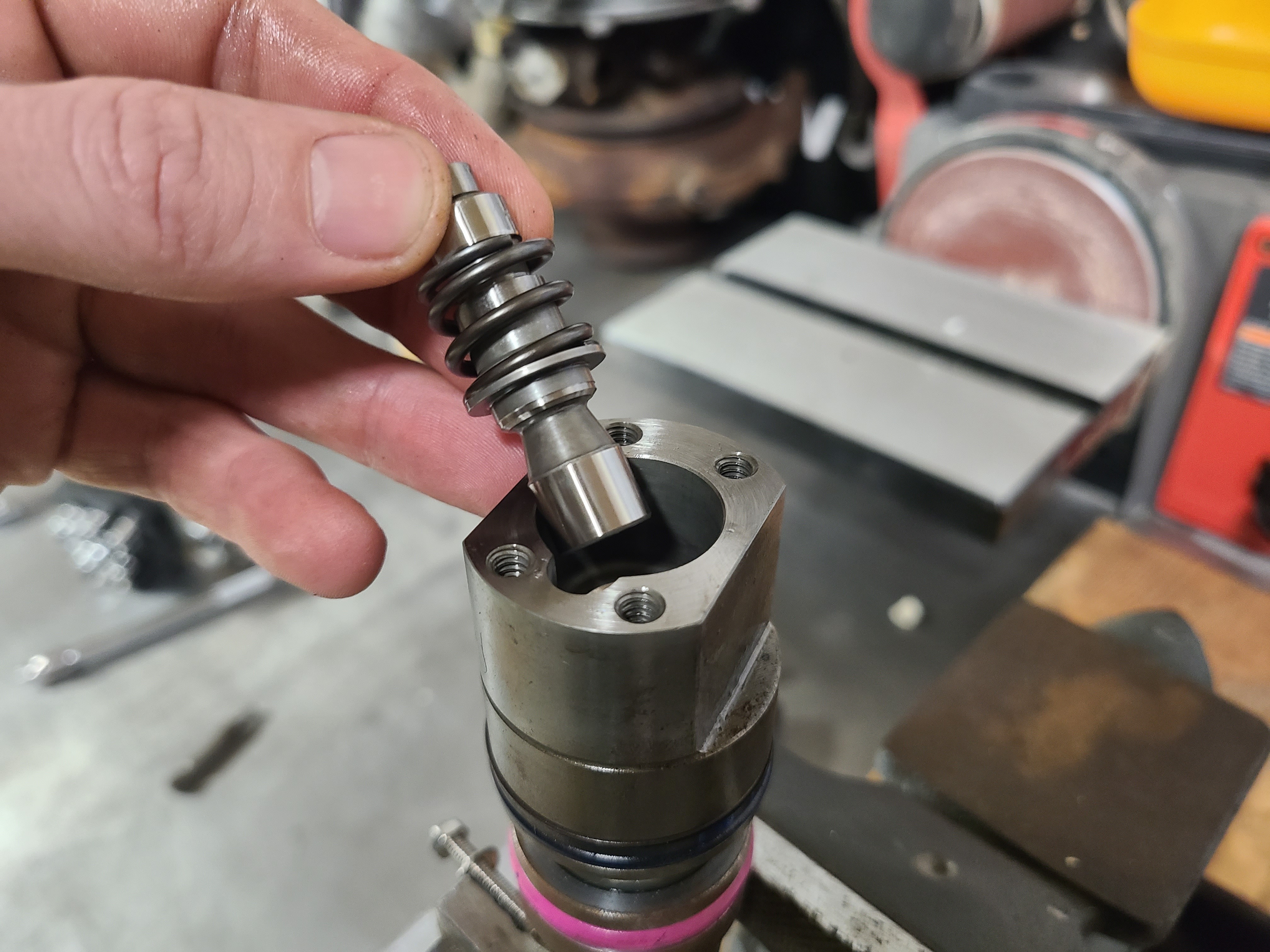
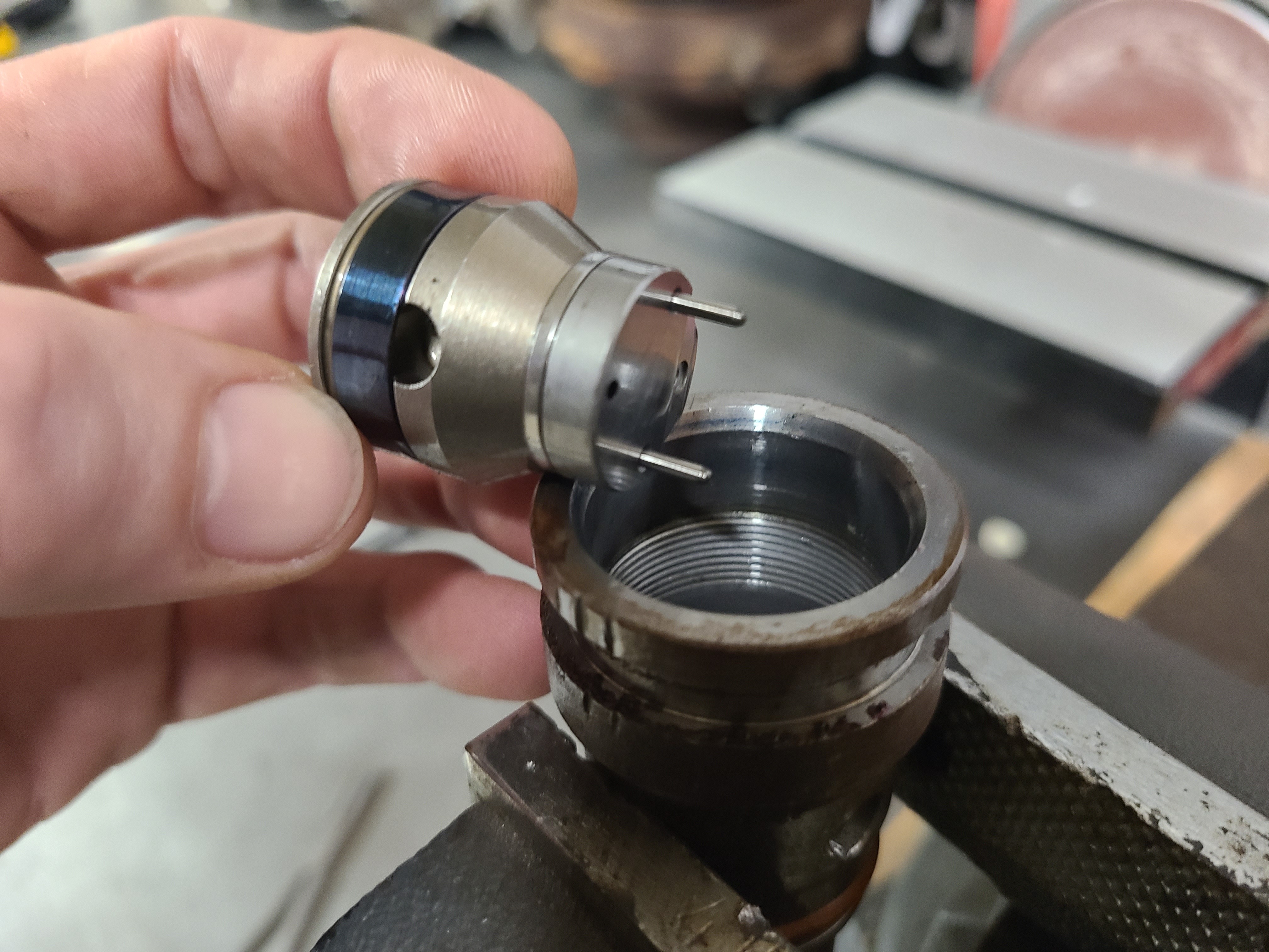
12 Amplifier / Fuel Side: Starting on the fuel side of things (although this is the grey line between the two/where the two intersect), with the upper body removed, we can access the Plunger section. Two pins exist here that are used to locate/clock the upper body to the lower, correctly. Those must be pulled before moving on.
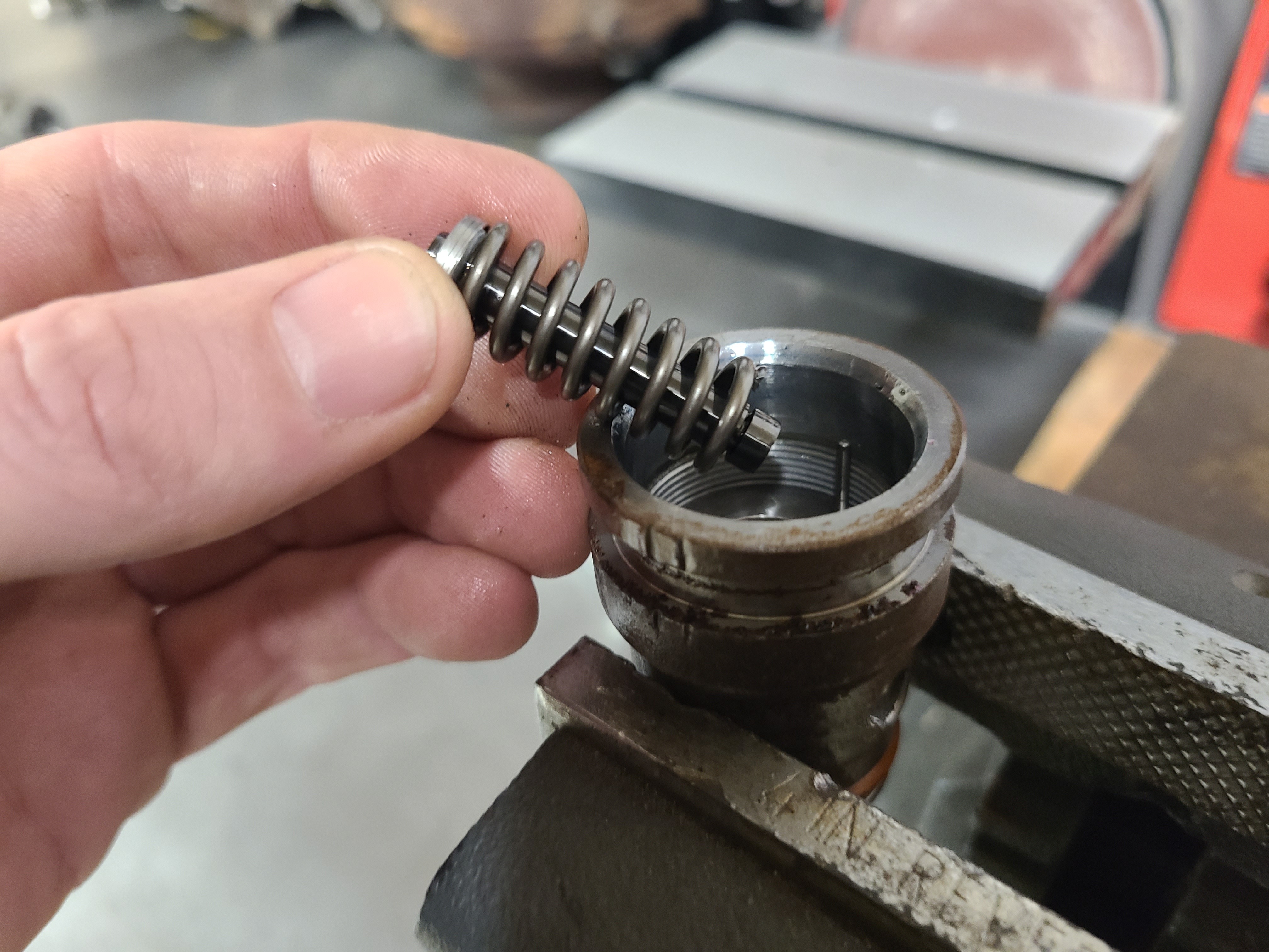
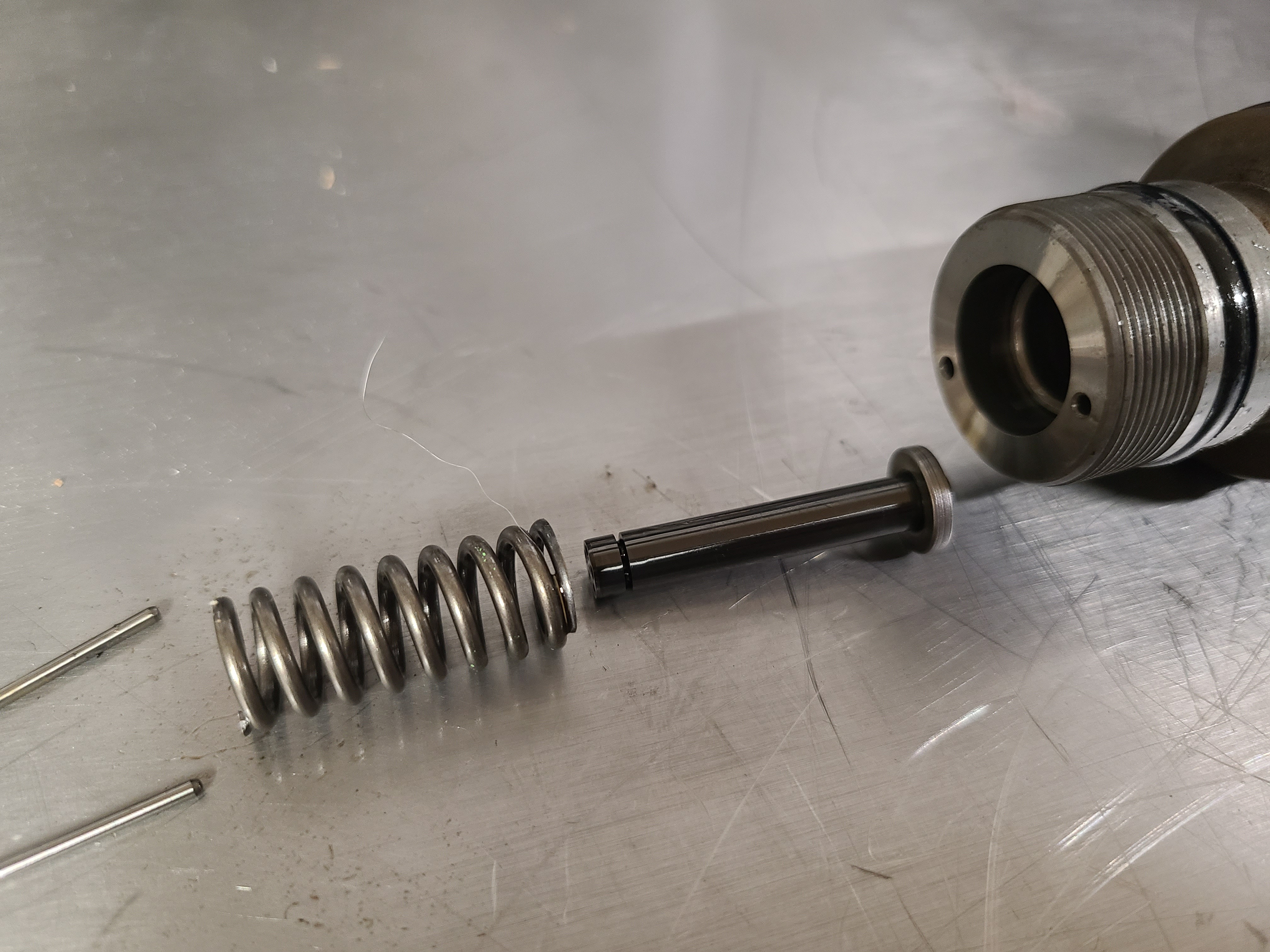
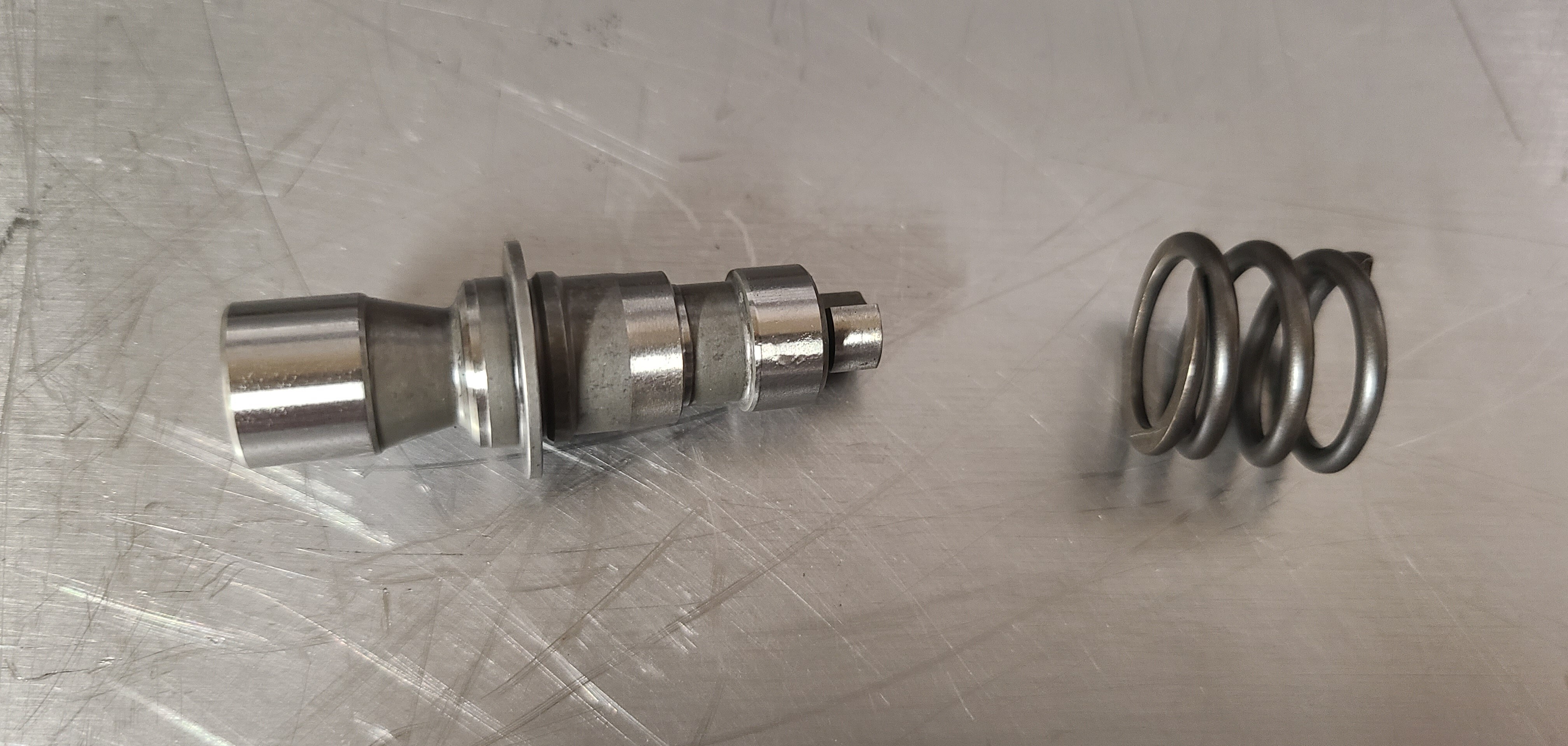
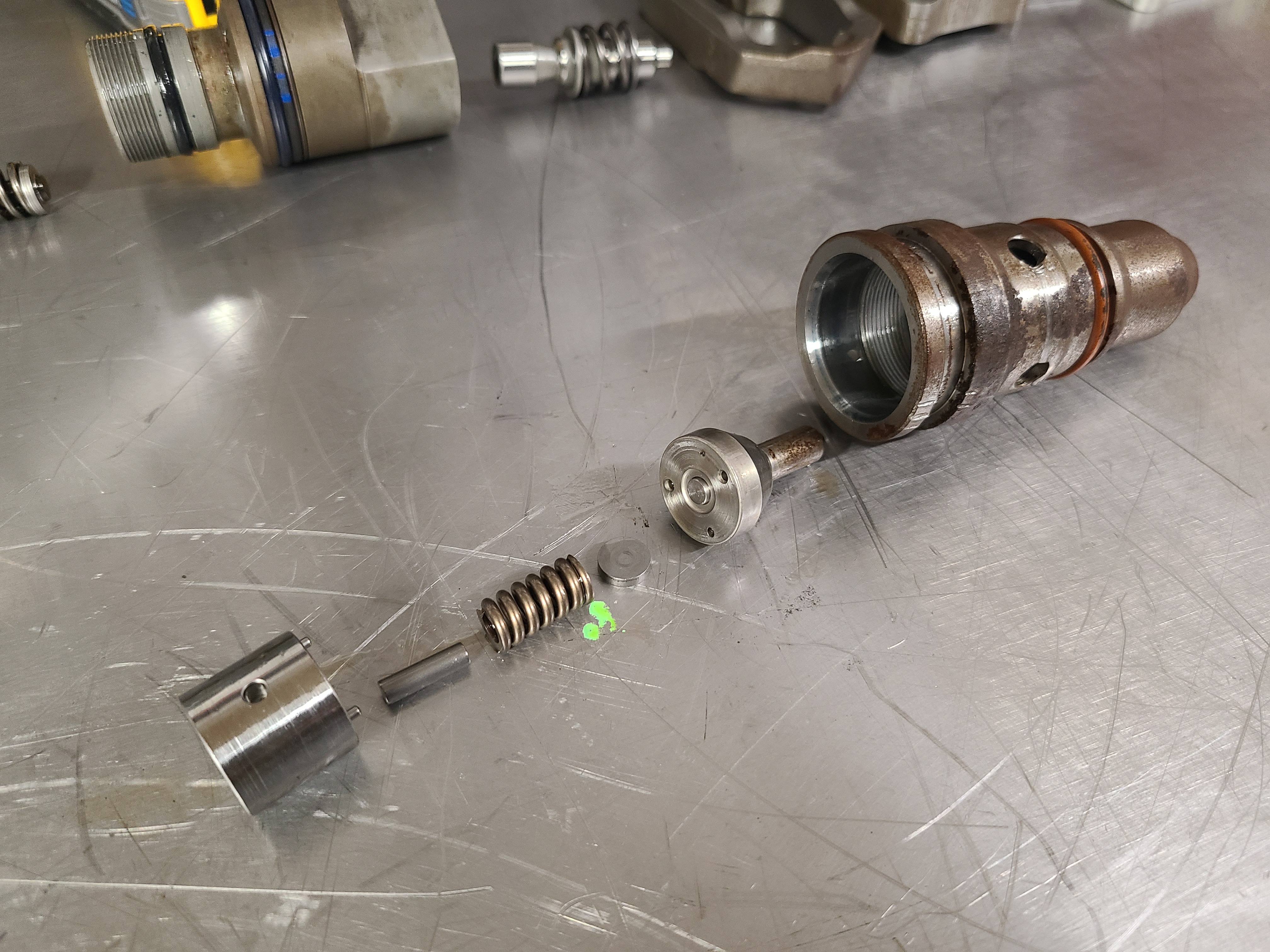
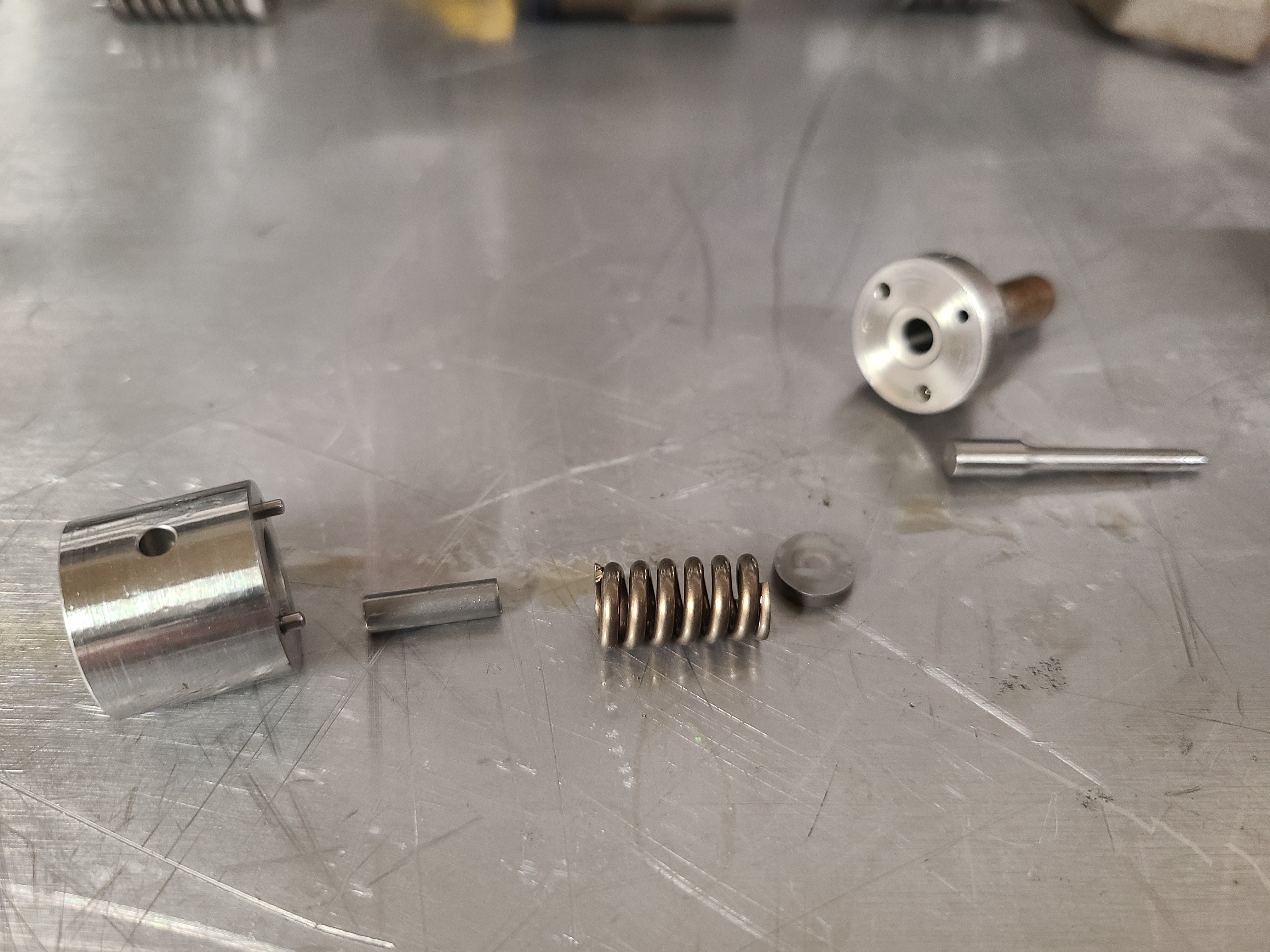
13-14 Plunger (Fuel Plunger) and Spring: The Amplifier Piston drives the Fuel Plunger down, and the Plunger pressurizes the fuel. Any scoring or leakage here reduces fuel volume and makes the injector weak. The spring returns the Amplifier and Plunger back to home after the injection event.
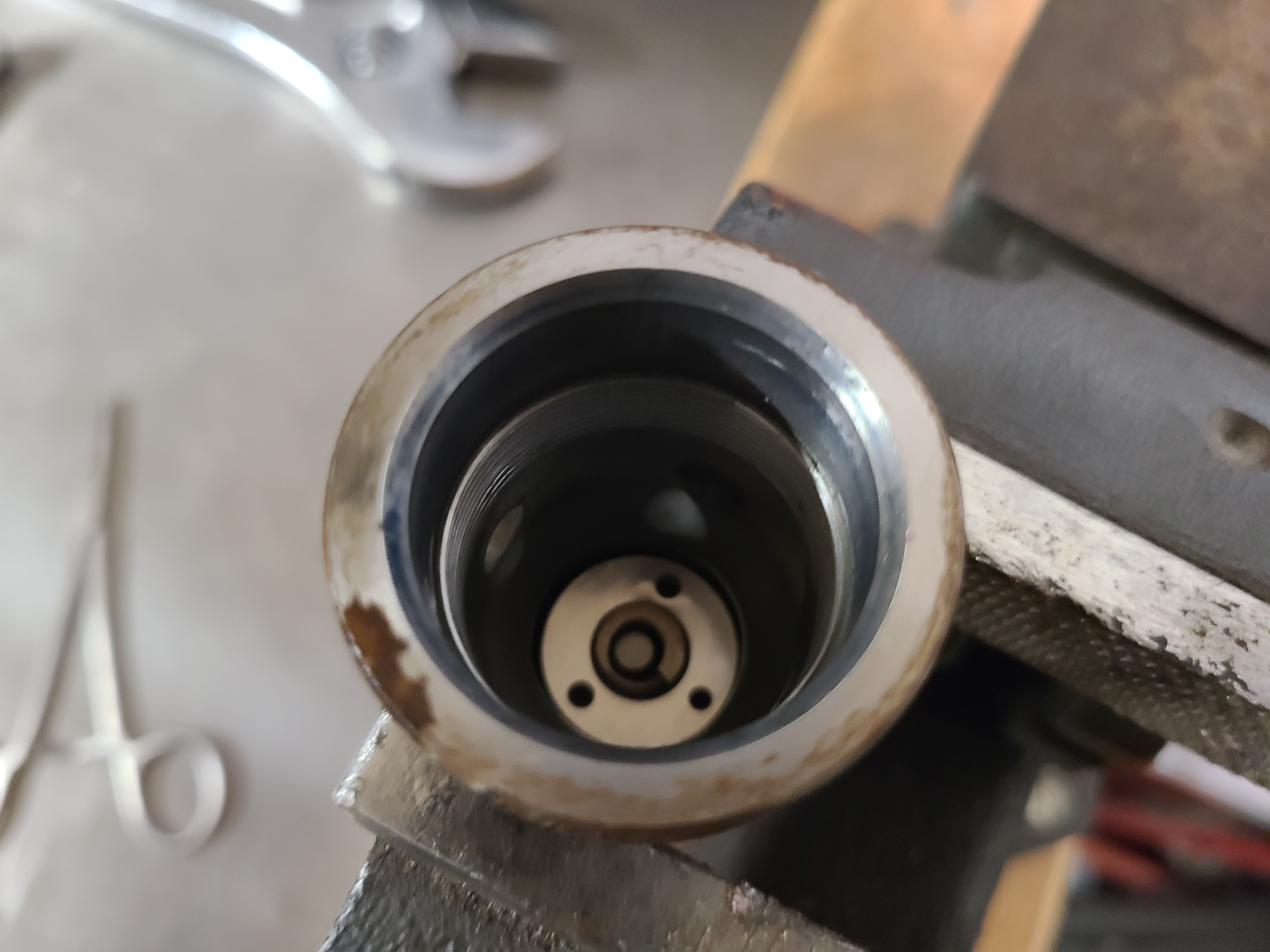
15 Barrel: The Barrel is the precision bore the Plunger rides in. Together, the Plunger and Barrel are the injector’s miniature high-pressure fuel pump. The Stop Plate and Stop usually come out with the Barrel (as seen on the tip of the Barrel). The two pins are used to locate/clock the Barrel correctly within the lower body.
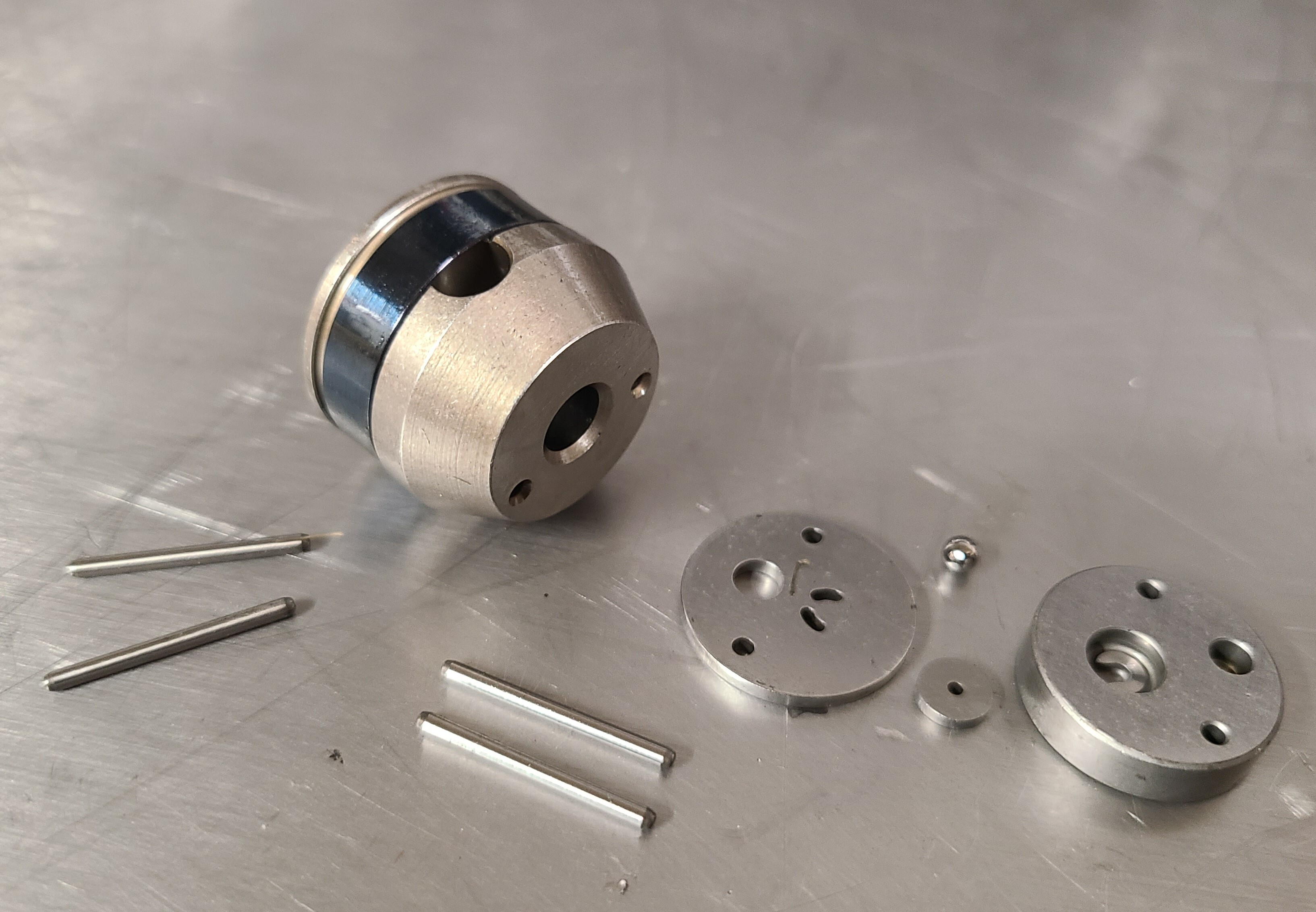
16 Barrel, Stop Plate, Check Ball, Check Plate, Stop (and four locating pins): These parts limit travel and keep the small fuel-control pieces from moving too far. They are simple parts, but damaged Stops can throw off injector timing and consistency.
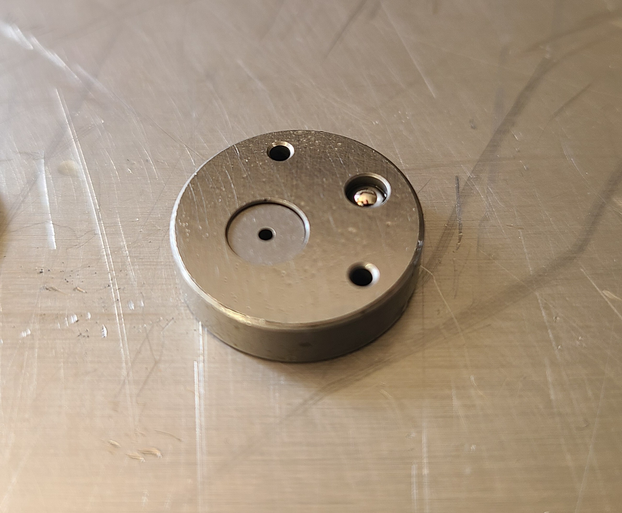
17 Stop: Within the "Stop" is a Check Ball and Check Plate. The check ball acts like a one-way valve inside the fuel circuit. If the ball or seat wears, pressure bleeds off and the injector loses clean fuel control.
18 – 20 Spacer Sleeve, Stop Pin, Nozzle Spring, Lift Spacer, Nozzle and Pintle: At this point the fuel has been pressurized and sent towards the nozzle. From the left is the Spacer Sleeve followed by the Stop Pin, Nozzle Spring, Lift Spacer and the Nozzle and Pintle. These parts set the spacing in the Nozzle and control Nozzle Pintle lift and return. Problems here make the injector sloppy in general with spray control becoming, well, uncontrollable.
21 Nozzle and Pintle: Last in the long stack of parts, the Nozzle and Nozzle Pintle. This is where the fuel gets sprayed into the cylinder. The Nozzle and Pintle are a matched set. Each Pintle is machined to its respective Nozzle. For stock 7.3 injectors, the nozzles have seven holes which the fuel sprays out of in a pattern designed to keep the fuel within the piston bowl, and atomized correctly. The Nozzle Spring keeps the Pintle seated while fuel pressure opens it for the injection event. Good working Nozzles and Pintles are very important to injector efficiency. Contamination, pitting and other wear will also make the injectors sloppy.
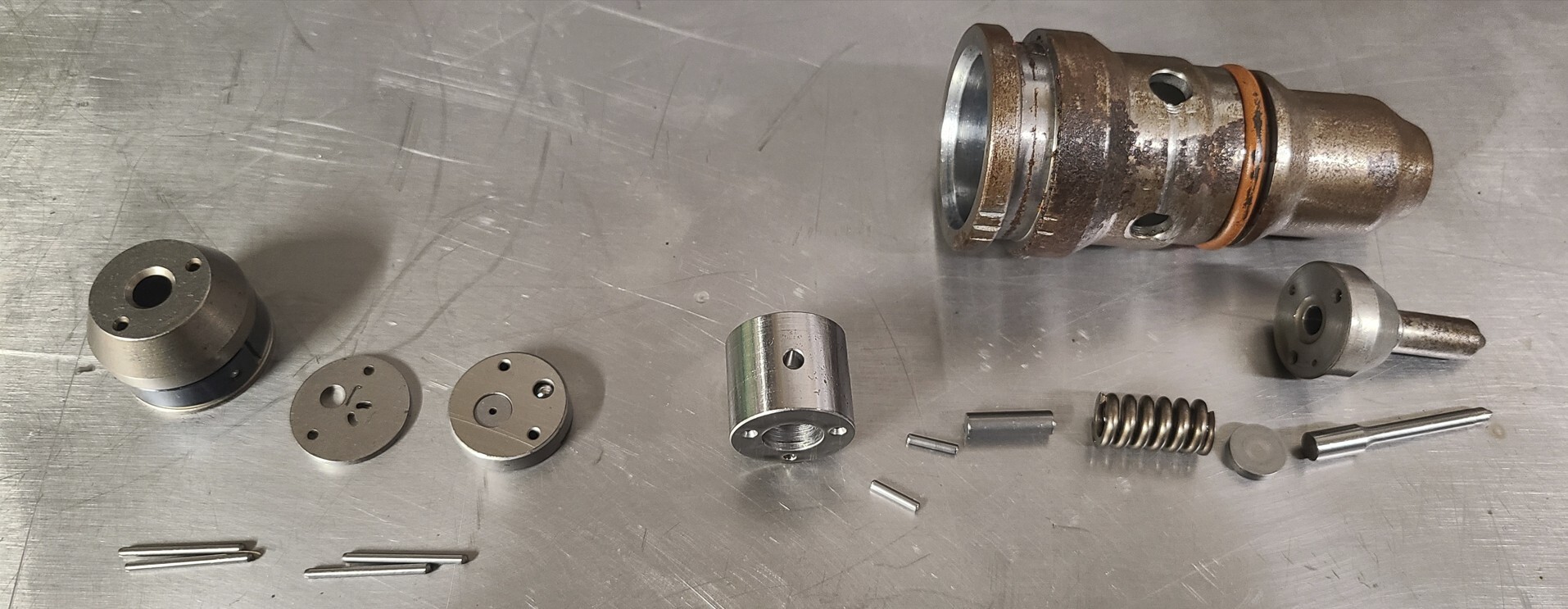
22 Lower Fuel Side Parts Laid Out


